
Guide

20 Intel
®
Celeron
®
D Processor for Embedded Applications Thermal Design Guide
Design Guidelines
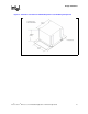
These dimensions are recommended to limit heatsink movement (rocking and sliding) during
lateral shock (x and y directions).
Requirement 2: Maximum mass and center of gravity (CG)
• The maximum combined mass of the heatsink/fan/shroud assembly is 450 grams.
• The combined center of gravity of the heatsink/fan/shroud assembly must be no greater than
0.85 inches above the motherboard.
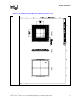
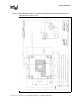
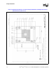
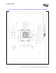
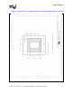
Figure 8 shows the heatsink, fan, and shroud assembly volumetric keep-in for the ATX form factor.
2.1.4 Retention Mechanism-1U and 2U Form Factor
The reference thermal solutions enabled by Intel for the 1U and 2U form factor are not attached to
the processor with the use of the standard reference retention mechanism and clip due to form
factor constraints. These reference design thermal solutions are attached to the processor using a
spring loaded fastener and a backplate. The PCB primary and secondary side keep-out
recommendations for these solutions are shown in Figure 6 and Figure 7 in Section 2.1.2,
“Motherboard Volumetric Constraint Requirements” on page 12. Information on the fastener may
be obtained from your Intel field sales representative.
If another method of attaching the thermal solution to the processor is desired, it must comply with
package and socket loading specification as delineated in Section 4.8, “Package and Socket Load
Specifications” on page 35.
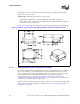
Figure 8. Heatsink, Fan, and Shroud Assembly Volumetric Constraint, ATX Form Factor
NOTE: All dimensions are in inches.