
Guide


24 Intel
®
Celeron
®
D Processor for Embedded Applications Thermal Design Guide
Characterizing Cooling Performance Requirements
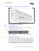
Figure 9 illustrates the combination of the different thermal characterization parameters.
3.1 Example of Cooling Performance
The cooling performance, Ψ
CA,
is defined using the principle of thermal characterization
parameter described above:
• Define a target case temperature T
CMax
and corresponding Thermal Design Power (TDP) at a
target frequency, F, given in the Intel Celeron D Datasheet.
• Define a target local ambient temperature at the processor, T
A
.
Since the processor thermal specifications (T
CMax
and TDP) may vary with the processor
frequency, it is important to identify the worst case (lowest Ψ
CA
) for a targeted chassis
(characterized by T
A
) to establish a design strategy such that a given heatsink can cover a given
range of processor frequencies.
The following example illustrates how one might determine the appropriate performance targets.
The example power and temperature numbers used here are not related to any Intel processor
thermal specifications and are for illustrative purposes only.
Assume the processor TDP is 89 W and the case temperature specification is 69° C for a given
frequency. Assume as well that the system airflow has been designed such that the local processor
ambient temperature is 42° C. The following could be calculated using Equation 1 from above for
the given frequency:
To determine the required heatsink performance, a heatsink solution provider would need to
determine Ψ
CS
performance for the selected TIM and mechanical load configuration. If the
heatsink solution were designed to work with a TIM material performing at Ψ
CS
≤ 0.1° C/W,
solving for Equation 2 from above, the performance of the heatsink would be:
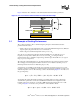
Figure 9. Processor Thermal Characterization Parameter Relationships
IHS
T
T
HEATSINK
IHS
PROCESSOR
T
C
A
SOCKET
Ψ
SA
Ψ
CS
Ψ
CA
TIM
S
ψ
CA
T
C
T
A
–()TDP⁄ 69 42–()89⁄ 0.303° C
W
⁄===
ψ
SA
ψ
CA
ψ
CS
– 0.303 0.1– 0.203° CW⁄===