
Guide

Intel
®
Celeron
®
D Processor for Embedded Applications Thermal Design Guide 27
Thermal Design Guidelines
4.0 Thermal Design Guidelines
This section presents thermal solution design guidelines for the Intel Celeron D Processor in the
478-pin package in three different form factors: desktop/ATX, 2U, and 1U server. The required
performance of the thermal solution is dependent on many parameters, including the processor’s
thermal design power (TDP), maximum case temperature (T
C max
), operating ambient temperature,
and system airflow. The guidelines and recommendations presented in this section are based on
specific parameters. It is the responsibility of each product design team to verify that thermal
solutions are suitable for their specific use.
The thermal metrology for the Intel Celeron D Processor must be followed to evaluate the thermal
performance of proposed cooling solutions. To develop a reliable thermal solution, all of the
appropriate variables must be considered. Thermal simulations and characterizations must be
carried out with all system parameters accounted for. The solutions presented in this document
must be validated as specified in their final intended system.
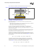
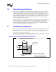
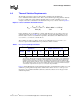
4.1 Processor Case Temperature
The case temperature is defined as the temperature measured at the center of the top surface of the
IHS. For illustration, the measurement location for a 35 mm x 35 mm FC-mPGA4 package is
shown in Figure 10. In case of conflict, the dimensions of the processor package in the datasheet
supercede the information in this document.
Techniques for measuring the case temperature are detailed the Intel
®
Pentium
®
4 Processor on 90
nm Process Thermal and Mechanical Design Guidelines.
Figure 10. Processor IHS Temperature Measurement Location
Measure from edge of processor
Measure T
at this point.
C
Thermal interface material
should cover the entire surface
of the Integrated Heat Spreade
r
0.689”
17.5 mm
0.689”
17.5 mm
35 mm x 35 mm Package
Package