
Guide

Intel
®
Celeron
®
D Processor for Embedded Applications Thermal Design Guide 31
Thermal Design Guidelines
requires 100 percent of the airflow to be ducted through the fins in order to prevent heatsink
bypass. A mechanical drawing of the enabled thermal solution can be seen in Figure 17 of the
appendix.
The primary and secondary side volumetric constraints for the 1U thermal solution can be seen in
Section 2.1.2, “Motherboard Volumetric Constraint Requirements” on page 12. This thermal
solution is attached to the processor package with the use of spring loaded fasteners attached to a
backplate on the bottom side of PCB.
Developers who want to design thermal solutions for the Intel Celeron D Processor in the 1U
server form factor need to ensure that it meets the thermal requirement stated in Section 4.4,
“Thermal Solution Requirements” on page 29. They must also adhere to the standard mechanical
volumetric constraints as stated in Section 2.1.2, “Motherboard Volumetric Constraint
Requirements” on page 12.
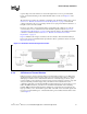
Figure 12 illustrates the z-height constraints of the 1U form factor. This mechanical stackup is
based on the Server System Infrastructure Specifications. These specifications may be viewed at
http://www.ssiforum.org.
4.5.3 2U Reference Thermal Solution
Intel has designed a reference thermal solution for the Intel Celeron D Processor for Embedded
Applications in the 2U form factor. This solution uses dense fin heat sink technology combined
with high speed airflow devices. This thermal solution has a relatively high pressure drop and
requires an airflow source that can provide the necessary amount of airflow to meet the component
and system thermal performance targets. The performance for this heatsink when used in
combination with a high speed fan and Shin-Etsu* G751 thermal grease, has shown a
Ψ
CA
= .315°
C/W at 34 CFM and 0.357 in_water. However, the final intended thermal solution including,
heatsink, TIM and attach mechanism must be validated by system integrators. In addition to the
high speed airflow source, this heatsink requires 100% of the airflow to be ducted through the fins
in order to prevent heatsink bypass. A mechanical drawing of the enabled thermal solution can be
seen in Figure 18.
Figure 12. 1U Thermal Solution Z-Height Constraints