
Guide


34 Intel
®
Celeron
®
D Processor for Embedded Applications Thermal Design Guide
Thermal Design Guidelines
4.6 Interface to Package Requirements
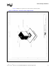
The Intel Celeron D Processor is packaged in a Flip-Chip Pin Grid Array (FC-mPGA4) package
technology. Refer to the
Intel Celeron D Processor Datasheet for detailed mechanical
specifications of the 478-pin package.
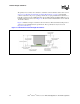
The package includes an integrated heat spreader (IHS). The IHS spreads non-uniform heat from
the die to the top of the IHS, out of which the heat flux is more uniform and on a larger surface
area. This allows more efficient heat transfer out of the package to an attached cooling device.
Note: Do not assume that the processor power is dissipated uniformly on the IHS. In particular, when
validating a thermal solution, an Intel Celeron D Processor thermal test vehicle shall be used, and a
correlation to real parts applied to the results. Refer to the
Intel
®
Pentium
®
4 Processor on 90 nm
Process Thermal and Mechanical Design Guidelines
for more information.
The IHS is designed to be the interface for mounting a heatsink. Details may be found in the
Intel
Celeron D Processor Datasheet
.
The processor connects to the motherboard through a ZIF surface mount socket. The socket is
described in the
Intel
®
Pentium
®
4 Processor, 478-Pin Socket (mPGA478B) Design Guidelines.
To facilitate customer assembly and ensure proper alignment and cooling performance, the
heatsink base must be designed for symmetrical assembly. Refer to Section 2.1.3.3, “Additional
Requirements for Solutions Using Reference ATX Heatsink and Reference Clip” on page 19 for
further information on the interface to the motherboard.
It is not recommended to use any portion of the interposer as a mechanical reference or
load-bearing surface in either static or dynamic compressive load conditions.
4.7 Thermal Interface Material Requirements
All thermal interface materials must be sized and positioned on the heatsink base in a way that
ensures that the entire processor IHS area is covered. It is important to compensate for
heatsink-to-processor attachment positional alignment when selecting the proper thermal interface
material size.
Note: When a pre-applied thermal interface material is specified, it may have a protective application
tape. This tape must be removed prior to heatsink attachment.
As overall performance of the processor cooling solution becomes more and more demanding,
TIM performance contribution must be carefully studied. In selecting the TIM, consider the
following (not an extended list):
• Compatibility with high volume manufacturing and assembly for installation.
• Minimal adhesion of the TIM that may create a strong bond between the heatsink and the
package, creating the following impacts:
— Potential package pullout from the actuated socket when removing the heatsink from the
processor for rework and servicing.
— Increased risk of package pullout from socket during shock and vibration events.
• Load needed on the heatsink/processor/socket assembly to ensure TIM performance (refer to
Section 4.8 for package load specifications).