
Document


Electrical Specifications
24 Datasheet
NOTES:
1. For functional operation, all processor electrical, signal quality, mechanical and thermal
specifications must be met.
2. Storage temperature is applicable to storage conditions only. In this scenario, the
processor must not receive a clock, and no lands can be connected to a voltage bias.
Storage within these limits does not affect the long-term reliability of the device. For
functional operation, please refer to the processor case temperature specifications.
3. This rating applies to the processor and does not include any tray or packaging.
4. Failure to adhere to this specification can affect the long term reliability of the processor.
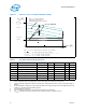
3.10 Processor DC Specifications
The processor DC specifications in this section are defined at the processor
core (pads) unless noted otherwise. See Table 4 for the pin signal definitions and
signal pin assignments. Most of the signals on the FSB are in the AGTL+ signal group.
The DC specifications for these signals are listed in Table 8. DC specifications for the
CMOS group are listed in Table 9.
Table 6 through Table 10 list the DC specifications and are valid only while meeting
specifications for junction temperature, clock frequency, and input voltages. Active
mode load line specifications apply in all states except in the Deep Sleep state.
V
CC,BOOT
is the default voltage driven by the voltage regulator at power up in order to
set the VID values. Unless specified otherwise, all specifications are at Tjunction =
100°C. Care should be taken to read all notes associated with each parameter.
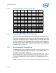
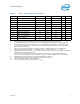
Table 5. Processor Absolute Maximum Ratings
Symbol Parameter Min Max Unit Notes
1
T
STORAGE
Processor storage
temperature
-40 85 °C 2, 3, 4
V
CC
Any processor supply voltage
with respect to V
SS
-0.3 1.55 V
V
inAGTL+
AGTL+ buffer DC input
voltage with respect to V
SS
-0.1 1.55 V
V
inAsynch_CMOS
CMOS buffer DC input
voltage with respect to V
SS
-0.1 1.55 V
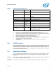
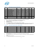
Table 6. DC Voltage and Current Specifications
Symbol Parameter Min Typ Max Unit Notes
V
CC
V
CC
of the Processor Core 0.95 1.15 1.30 V 1, 2
V
CC,BOOT
Default V
CC
Voltage for Initial Power Up 1.20 V 2, 8
V
CCP
AGTL+ Termination Voltage 1.00 1.05 1.10 V
V
CCA
PLL Supply Voltage 1.425 1.5 1.575 V
I
CCDES
I
CC
for processors
Recommended Design Targets:
36 A 5