
Document


Datasheet 25
Electrical Specifications
NOTES:
1. Each processor is programmed with a maximum valid voltage identification value (VID), which is set at
manufacturing and can not be altered. Individual maximum VID values are calibrated during
manufacturing such that two processors at the same frequency may have different settings within the VID
range.
2. The voltage specifications are assumed to be measured across V
CC_SENSE
and V
SS_SENSE
pins at the socket
with a 100-MHz bandwidth oscilloscope, 1.5-pF maximum probe capacitance, and 1-MΩ minimum
impedance. The maximum length of ground wire on the probe should be less than 5 mm. Ensure external
noise from the system is not coupled in the scope probe.
3. Specified at 100°C Tj.
4. Specified at the VID voltage.
5. The I
CCDES
(max) specification of 36-A comprehends only the processor.
6. Based on simulations and averaged over the duration of any change in current. Specified by design/
characterization at nominal V
CC
. Not 100% tested.
7. Measured at the bulk capacitors on the motherboard.
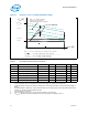
8. V
CC,
BOOT
tolerance shown in Figure 3.
9. This is a steady-state Iccp current specification, which is applicable when both V
CCP
and V
CC_CORE
are high.
10. This is a power-up peak current specification, which is applicable when V
CCP
is high and V
CC_CORE
is low.
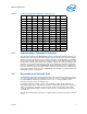
I
CC
I
CC
for processors A
Processor
Number
Frequency Die Variant
530
540
550
560
1.73 GHz
1.86 GHz
2.00 GHz
2.13 GHz
1-M Fused
1 M
1-M Fused
1 M
1-M Fused
1 M
1-M Fused
1 M
34.5
32.0
34.5
32.0
34.5
32.0
34.5
32.0
A3, 4
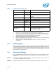
I
AH
,
I
SGNT
I
CC
Auto-Halt & Stop-Grant 21 A 3, 4
I
SLP
I
CC
Sleep 20.5 A 3, 4
I
DSLP
I
CC
Deep Sleep 18.6 A 3, 4
dI
CC/DT
V
CC
Power Supply Current Slew Rate at
CPU Package Pin
600 A/µs 6, 7
I
CCA
I
CC
for V
CCA
Supply 130 mA
I
CCP
I
CC
for V
CCP
Supply before V
CC
Stable
I
CC
for V
CCP
Supply after V
CC
Stable
4.5
2.5
A
A
9
10
Table 6. DC Voltage and Current Specifications
Symbol Parameter Min Typ Max Unit Notes