
Intel Celeron Processor Specification Update

INTEL
®
CELERON® PROCESSOR SPECIFICATION UPDATE
98
Instruction Set Reference
Section Opcode Instruction Addition
Addition
to Page
“Comments”
section
FSTCW/FNSTCW-Store
Control Word
9B D9 /7 FSTCW
m2byte
Add “Comments”
section with
clarification phrase
3-250
FSTENV/FNSTENV-Store
FPU Environment
9B D9 /6 FSTENV
m14/28byte
Add “Comments”
section with
clarification phrase
3-253
9B DD /7 FSTSW
m2byte
FSTSW/FNSTSW-Store
Status Word
9B DF E0 FSTSW AX
Add “Comments”
section with
clarification phrase
3-256
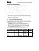
C3. MTRR Initialization Clarification
The following sentence should be added to the end of the first paragraph of Section 9.12.5 of the Intel
Architecture Software Developer’s Manual
, Volume 3: System Programming Guide: “The MTRRs must be
disabled prior to initialization or modification.”
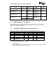
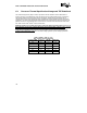
C4. Non-AGTL+ Output Low Current Clarification
In Table 6 of the Intel
®
Celeron
®
Processor Datasheet, the note in bold should be added:
Symbol Parameter Min Max Unit Notes
VIL Input Low Voltage -0.3 0.7 V
VIH Input High Voltage 1.7 2.625 V 2.5 V +5% maximum
VOL Output Low Voltage 0.4 V 2
VOH Output High Voltage N/A 2.625 V All outputs are open-
drain to 2.5 V +5%
IOL Output Low Current 14 mA 5
IL Leakage Current for Inputs,
Outputs, and I/O
±100 μA
3, 4
Notes:
1. Unless otherwise noted, all specifications in this table apply to all Celeron processor frequencies.
2. Parameter measured at 14 mA (for use with TTL inputs).
3.
(0 ≤ VIN ≤ 2.5 V +5%).
4.
(0 ≤ VOUT ≤ 2.5 V +5%).
5. Specified as the minimum amount of current that the output buffer must be able to sink. However, VOL_MAX
cannot be guaranteed if this specification is exceeded.