
Uncore Manual

Uncore Performance Monitoring
IRP Performance Monitoring
100 Reference Number: 329468-002
2.6.3.1 IRP Box Level PMON State
The following registers represent the state governing all box-level PMUs in the IRP Box.
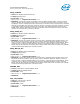
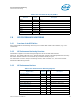
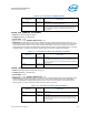
In the case of the IRP, the IRP_PCI_PMON_BOX_CTL register provides the ability to manually freeze the
counters in the box (.frz) and reset the generic state (.rst_ctrs and .rst_ctrl).
Table 2-106. IRP_PCI_PMON_BOX_CTL Register – Field Definitions
U
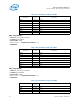
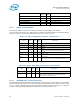
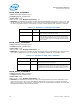
Table 2-107. IRP_PCI_PMON_BOX_STATUS Register – Field Definitions
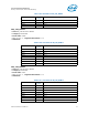
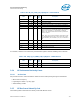
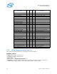
2.6.3.2 IRP PMON state - Counter/Control Pairs
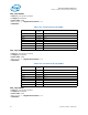
The following table defines the layout of the IRP performance monitor control registers. The main task
of these configuration registers is to select the event to be monitored by their respective data counter
(.ev_sel, .umask). Additional control bits are provided to shape the incoming events (e.g. .edge_det,
.thresh) as well as provide additional functionality for monitoring software (.rst).
Generic Counters
IRP1_PCI_PMON_CTR1 C0 64 IRP 1 PMON Counter 1
IRP1_PCI_PMON_CTR0 B8 64 IRP 1 PMON Counter 0
IRP0_PCI_PMON_CTR1 B0 64 IRP 0 PMON Counter 1
IRP0_PCI_PMON_CTR0 A0 64 IRP 0 PMON Counter 0
Field Bits Attr
HW
Reset
Val
Description
ig 31:18 RV 0 Ignored
rsv 17:16 RV 0 Reserved; SW must write to 1 else behavior is undefined.
ig 15:9 RV 0 Ignored
frz 8 WO 0 Freeze.
If set to 1 the counters in this box will be frozen.
ig 7:2 RV 0 Ignored
rst_ctrs 1 WO 0 Reset Counters.
When set to 1, the Counter Registers will be reset to 0.
rst_ctrl 0 WO 0 Reset Control.
When set to 1, the Counter Control Registers will be reset to
0.
Field Bits Attr
HW
Reset
Val
Description
ig 31:4 RV 0 Ignored
ov 3:0 RW1C 0 If an overflow is detected from the corresponding
IRP_PCI_PMON_CTR register, it’s overflow bit will be set.
NOTE: Write of ‘1’ will clear the bit.
Register Name
PCICFG
Address
Size
(bits)
Description