
Uncore Manual


Reference Number: 329468-002 131
Uncore Performance Monitoring
Intel® QPI Link Layer Performance Monitoring
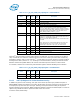
VR_HOT_CYCLES
• Title: VR Hot
• Category: VR_HOT Events
• Event Code: 0x32
• Max. Inc/Cyc:. 1, Register Restrictions: 0-3
• Definition:
2.8 INTEL® QPI LINK LAYER PERFORMANCE MONITORING
2.8.1 Overview of the Intel® QPI Box
The Intel
®
QPI Link Layer is responsible for packetizing requests from the caching agent on the way
out to the system interface. As such, it shares responsibility with the CBo(s) as the Intel QPI caching
agent(s). It is responsible for converting CBo requests to Intel QPI messages (i.e. snoop generation
and data response messages from the snoop response) as well as converting/forwarding ring
messages to Intel QPI packets and vice versa.On Ivy Bridge, Intel® QPI is split into two separate
layers. The Intel® QPI LL (link layer) is responsible for generating, transmitting, and receiving
packets with the Intel® QPI link.
R3QPI (Section 2.10, “R3QPI Performance Monitoring”) provides the interface to the Ring for the Link
Layer. It is also the point where VNA/VN0 link credits are acquired.There are two Intel® QPI agents
in Ivy Bridge that share a single ring stop and a third agent in the EX part with its own ring stop. These
links can be connected to a single destination (such as in DP), but also can be connected to two sepa-
rate destinations (4s Ring or sDP). Therefore, it will be necessary to count Intel® QPI statistics for
each agent seperately.The Intel® QPI Link Layer processes two flits per cycle in each direction. In
order to accommodate this, many of the events in the Link Layer can increment by 0, 1, or 2 in each
cycle. It is not possible to monitor Rx (received) and Tx (transmitted) flit information at the same
time on the same counter.
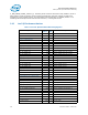
2.8.2 Intel® QPI Performance Monitoring Overview
Each Intel
®
QPI Port supports event monitoring through four 48b wide counters
(Q_Py_PCI_PMON_CTR/CTL{3:0}). Each of these four counters can be programmed to count any
Intel
®
QPI event. The Intel
®
QPI counters can increment by a maximum of 8b per cycle.
Each Intel
®
QPI Port also includes a mask/match register that allows a user to match packets,
according to various standard packet fields such as message class, opcode, etc, as they leave the QPI
Port.
For information on how to setup a monitoring session, refer to Section 2.1, “Uncore Per-Socket
Performance Monitoring Control”
.
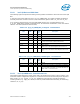
2.8.2.1 QPI PMON Registers - On Overflow and the Consequences (PMI/Freeze)
If an overflow is detected from a QPI performance counter enabled to communicate its overflow
(Q_Py_PCI_PMON_CTL.ov_en is set to 1), the overflow bit is set at the box level
(Q_Py_PCI_PMON_BOX_STATUS.ov) and an overflow message is sent to the UBox. When the UBox
receives the overflow signal, the U_MSR_PMON_GLOBAL_STATUS.ov_q bit corresponding to the QPI
Port generating the overflow is set (see Table 2-3, “U_MSR_PMON_GLOBAL_STATUS Register – Field
Definitions”) and a PMI can be generated.
Once a freeze has occurred, in order to see a new freeze, the overflow field responsible for the freeze,
must be cleared by setting the corresponding bit in Q_Py_PCI_PMON_BOX_STATUS.ov and