
Uncore Manual


Reference Number: 329468-002 133
Uncore Performance Monitoring
Intel® QPI Link Layer Performance Monitoring
2.8.3.1 Intel® QPI Box Level PMON State
The following registers represent the state governing all box-level PMUs in each Port of the Intel
®
QPI
Box.
In the case of the Intel
®
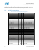
QPI Ports, the Q_Py_PCI_PMON_BOX_CTL register provides the ability to
manually freeze the counters in the box (.frz) and reset the generic state (.rst_ctrs and .rst_ctrl).
If an overflow is detected from one of the QPI PMON registers, the corresponding bit in the
Q_Py_PCI_PMON_BOX_STATUS.ov field will be set. To reset these overflow bits, a user must write a
value of ‘1’ to them (which will clear the bits).
Table 2-129. Q_Py_PCI_PMON_BOX_CTL Register – Field Definitions
U
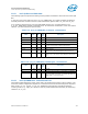
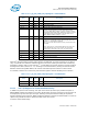
Table 2-130. Q_Py_PCI_PMON_BOX_STATUS Register – Field Definitions
2.8.3.2 Intel® QPI PMON state - Counter/Control Pairs
The following table defines the layout of the Intel
®
QPI performance monitor control registers. The
main task of these configuration registers is to select the event to be monitored by their respective
data counter (.ev_sel, .umask, .ev_sel_ext). Additional control bits are provided to shape the
incoming events (e.g. .edge_det, .thresh) as well as provide additional functionality for monitoring
software (.rst,.ov_en).
Field Bits Attr
HW
Reset
Val
Description
ig 31:18 RV 0 Ignored
rsv 17:16 RV 0 Reserved; SW must write to 1 else behavior is undefined.
ig 15:9 RV 0 Ignored
frz 8 WO 0 Freeze.
If set to 1 the counters in this box will be frozen.
ig 7:2 RV 0 Ignored
rst_ctrs 1 WO 0 Reset Counters.
When set to 1, the Counter Registers will be reset to 0.
rst_ctrl 0 WO 0 Reset Control.
When set to 1, the Counter Control Registers will be reset
to 0.
Field Bits Attr
HW
Reset
Val
Description
ig 31:5 RV 0 Ignored
rsv 4 RV 0 Reserved; SW must write to 0 else behavior is undefined.
ov 3:0 RW1C 0 If an overflow is detected from the corresponding
Q_Py_PCI_PMON_CTR register, it’s overflow bit will be set.
NOTE: Write of ‘1’ will clear the bit.