
Uncore Manual


Uncore Performance Monitoring
Intel® QPI Link Layer Performance Monitoring
134 Reference Number: 329468-002
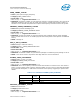
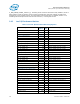
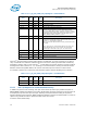
Table 2-131. Q_Py_PCI_PMON_CTL{3-0} Register – Field Definitions
The Intel
®
QPI performance monitor data registers are 48b wide. A counter overflow occurs when a
carry out from bit 47 is detected. Software can force all uncore counting to freeze after N events by
preloading a monitor with a count value of 2
48
- N and setting the control register to send an overflow
message to the UBox (Section 2.1.1.1, “Freezing on Counter Overflow”). During the interval of time
between overflow and global disable, the counter value will wrap and continue to collect events.
If accessible, software can continuously read the data registers without disabling event collection.
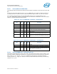
Table 2-132. Q_Py_PCI_PMON_CTR{3-0} Register – Field Definitions
2.8.3.3 Intel® QPI Registers for Packet Mask/Match Facility
In addition to generic event counting, each port of the Intel
®
QPI Link Layer provides two pairs of
MATCH/MASK registers that allow a user to filter packet traffic serviced (crossing from an input port to
an output port) by the Intel
®
QPI Link Layer. Filtering can be performed according to the packet
Opcode, Message Class, Response, HNID and Physical Address. Program the selected QPI LL counter to
capture CTO_COUNT in order to capture the filter match as an event.
To use the match/mask facility:
Field Bits Attr
HW
Reset
Val
Description
thresh 31:24 RW-V 0 Threshold used in counter comparison.
rsv 23 RV 0 Reserved. SW must write to 0 else behavior is undefined.
en 22 RW-V 0 Local Counter Enable.
ev_sel_ext 21 RW-V 0 Extension bit to the Event Select field.
ov_en 20 RW-V 0 When this bit is asserted and the corresponding counter
overflows, its overflow bit is set in the local status register
(Q_Py_PCI_PMON_BOX_STATUS.ov) and an overflow is sent on
the message channel to the UBox. When the overflow is received
by the UBox, the bit corresponding to this QPI will be set in
U_MSR_PMON_GLOBAL_STATUS.ov_q{1,0}.
ig 19 RV 0 Ignored
edge_det 18 RW-V 0 When set to 1, rather than measuring the event in each cycle it
is active, the corresponding counter will increment when a 0 to 1
transition (i.e. rising edge) is detected.
When 0, the counter will increment in each cycle that the event
is asserted.
NOTE: .edge_det is in series following.thresh. Due to this, the
.thresh field must be set to a non-0 value. For events that
increment by no more than 1 per cycle, set .thresh to 0x1.
rst 17 WO 0 When set to 1, the corresponding counter will be cleared to 0.
rsv 16 RV 0 Reserved. SW must write to 0 else behavior is undefined.
umask 15:8 RW-V 0 Select subevents to be counted within the selected event.
ev_sel 7:0 RW-V 0 Select event to be counted.
Field Bits Attr
HW
Reset
Val
Description
ig 63:48 RV 0 Ignored
event_count 47:0 RW-V 0 48-bit performance event counter