
Uncore Manual

Reference Number: 329468-002 79
Uncore Performance Monitoring
Memory Controller (iMC) Performance Monitoring
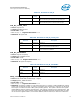
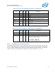
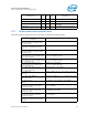
Table 2-72. MC_CHy_PCI_PMON_BOX_CTL Register – Field Definitions
U
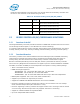
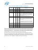
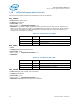
Table 2-73. MC_CHy_PCI_PMON_BOX_STATUS Register – Field Definitions
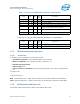
2.5.4.2 MC PMON state - Counter/Control Pairs
The following table defines the layout of the MC performance monitor control registers. The main task
of these configuration registers is to select the event to be monitored by their respective data counter
(.ev_sel, .umask). Additional control bits are provided to shape the incoming events (e.g. .edge_det,
.thresh) as well as provide additional functionality for monitoring software (.rst,.ov_en).
Field Bits Attr
HW
Reset
Val
Description
ig 31:18 RV 0 Ignored
rsv 17:16 RV 0 Reserved; SW must write to 1 else behavior is undefined.
ig 15:9 RV 0 Ignored
frz 8 WO 0 Freeze.
If set to 1 the counters in this box will be frozen.
ig 7:2 RV 0 Ignored
rst_ctrs 1 WO 0 Reset Counters.
When set to 1, the Counter Registers will be reset to 0.
rst_ctrl 0 WO 0 Reset Control.
When set to 1, the Counter Control Registers will be reset to
0.
Field Bits Attr
HW
Reset
Val
Description
ig 31:6 RV 0 Ignored
rsv 5 RV 0 Reserved. SW must write to 0 else behavior is undefined.
ov 4:0 RW1C 0 If an overflow is detected from the corresponding
MC_CHy_PCI_PMON_CTR register, it’s overflow bit will be set.
NOTE: Write of ‘1’ will clear the bit.
Bit 4 -overflow for *_PMON_CTR4
Bit 1 -overflow for *_PMON_CTR1
Bit 0 -overflow for the fixed counter