
Personal Computer User Manual

Intel
®
820E Chipset
R
Design Guide 121
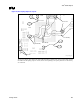
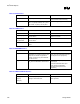
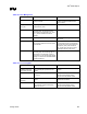
Figure 77. Dual-Footprint Analog Interface
IO_subsys_dual_footprint_analog_
IF
Magnetics
module
TDP
RJ45
Intel
®
82562EH/82562ET
TDN
RDP
RDN
RJ11
TXP
TXN
Tip
Ring
Intel
82562EH
config.
Intel
82562ET
config.
Additional guidelines for this configuration are as follows:
• L = 0.5 inch to 6.5 inches
• Stub = <0.5 inch
• Either the Intel 82562EH or Intel 82562ET/82562EM component can be installed. Not both.
• Pins 28, 29, and 30 of the Intel 82562ET component overlap pins 17, 18, and 19 of the Intel
82562EH component.
• Overlapping pins are tied to ground.
• No other signal pads should overlap or touch.
• Signal lines LAN_CLK, LAN_RSTSYNC, LAN_RXD[0], LAN_TXD[0], RDP, RDN, RXP/Ring,
and RXN/Tip are shared by the Intel
82562EH and Intel 82562ET component configurations.
• No stubs should be present when the Intel 82562ET component is installed.
• The packages used for the dual footprint are the TQFP for the Intel 82562EH component and the
SSOP for the Intel
82562ET component.
• A 22 Ω resistor can be placed at the driving side of the signal line to improve signal quality on the
LAN connect interface.
• Resistors should be placed as close as possible to components.
• Use components that can satisfy both the Intel 82562ET and Intel 82562EH component
configurations (i.e., a magnetics module).
• Install components for either the Intel 82562ET or Intel 82562EH component configuration. Only
one configuration can be installed at a time.
• Route shared signal lines such that stubs are not present or are minimized.
• Stubs may occur on shared signal lines (i.e., RDP and RDN). These stubs result from traces routed
to an uninstalled component.
• Use 0 Ω resistors to connect and disconnect circuitry not shared by both configurations. Place
resistor pads along the signal line to reduce stub lengths.
• Refer to the Intel 820E CRB layout for routing examples.