
Personal Computer User Manual

Intel
®
820E Chipset
R
36 Design Guide
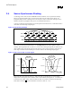
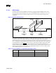
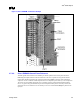
The following figure shows a top view of the trace width/spacing requirements for the RSL signals.
Figure 14. RSL Routing Diagram
RSL Signal Trace
Space
Ground
Space
RSL Signal Trace
Space
Ground
Space
18 mils
6 mils
10 mils
10 mils
6 mils
6 mils
18 mils
6 mils
rsl_route_dia
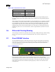
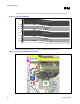
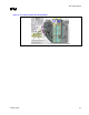
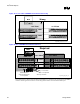
The following two figures show the top view of an example RSL breakout and route.
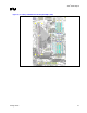
Figure 15. Primary-Side RSL Breakout Example