
Personal Computer User Manual

Intel
®
820E Chipset
R
Design Guide 59
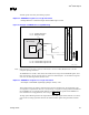
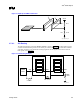
All RSL signals are routed adjacent to a ground reference plane. This includes all signals from
the last RIMM to the termination. If signals are routed on the bottom from the last RIMM to
the termination, the ground reference plane on the 3
rd
layer must extend under these signals
and include the ground side of the V
TERM
decoupling capacitors.
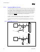
CTABs must not cross (or be on top of) power plane splits. They must be entirely referenced
to ground.
At least 10 mils of ground flood isolation is required around all RSL signals. (Ground isolation
must be exactly 6 mils from RSL signals.) Ground flood is recommended for isolation. This
ground flood should be as close as possible to the MCH (and the first RIMM). If possible,
connect the flood to the ground balls/pins on the MCH/connector.
• Clean V
REF
routing
Ensure a 1 × 0.1 µF capacitor on V
REF
at each connector.
Use a 10 mil-wide trace (6 mils minimum).
Do not route V
REF
near high-speed signals.
• RSL routing
All signals must be length-matched within ±10 mils of the nominal RSL length. (Note: Use the
table in the Intel
®
820 Chipset Family: 82820 Memory Controller Hub (MCH) Datasheet to
verify the trace lengths.) Ensure that signals with a dummy via are compensated correctly.
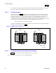
ALL RSL signals must have one via near the MCH BGA pad. Signals routed on the secondary
side of the MB will have a “real via,” while signals routed on the primary side will have a
“dummy via.” Additionally, all signals with a dummy via must have an additional trace length
of 25 mils.
B-side RIMM connector signals are routed on the secondary side of the motherboard. A-side
RIMM connector signals are routed on the primary side of the motherboard.
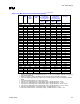
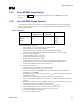
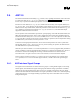
Signals must “alternate” layers, as shown in the following table:
If Signal Routed from MCH
to 1st RIMM on:
Then Route Signal from 1st RIMM
to Next RIMM on:
Primary side Secondary side
Secondary side Primary side
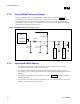
• Clock routing
Clock signals must be routed as a differential pair. The traces must be 14 mils wide and 6 mils
apart (with no ground isolation) when they are routed as a differential pair. For very short
sections under the MCH and under the first RIMM, it will not be possible to route as a
differential pair. In these sections, the clocks signals must neck up to 18 mils and be ground-
isolated with at least 10 mils ground isolation.
Clock signals must be length-compensated (using the 1.021 length factor mentioned in Section
2.8.3 2×/4× Timing Domain Routing Guidelines, 2×/4× Timing Domain Routing Guidelines).
Ensure that each clock pair is length-matched within ±2 mils.
When clock signals serpentine, they must serpentine together (to maintain differential 14:6
routing).
22 mil ground isolation is required on each side of the differential pair.