
Personal Computer User Manual

Intel
®
820E Chipset
R
60 Design Guide
2.8. AGP 2.0
For detailed AGP interface functionality (e.g., protocols, rules, signaling mechanisms), refer to Revision
2.0 of the latest AGP Interface Specification obtainable from http://www.agpforum.org
. This document
focuses only on specific Intel 820E chipset platform recommendations.
Revision 2.0 of the AGP Interface Specification enhances the functionality of the original AGP Interface
Specification (Rev. 1.0) by allowing 4× data transfers (4 data samples per clock) and 1.5 V operation. In
addition to these major enhancements, additional performance enhancement and clarifications (e.g., fast-
write capability) are included in the AGP Interface Specification (Rev. 2.0). The Intel 820E chipset
supports the enhanced features of AGP 2.0.
The 4× operation of the AGP interface provides for “quad-pumping” of the AGP AD (address/data) and
SBA (side-band addressing) buses. That is, data is sampled four times during each 66 MHz AGP clock.
This means that each data cycle is ¼ of a 15-ns (66 MHz) clock, or 3.75 ns. It is important to realize that
3.75 ns is the data cycle time, not the clock cycle time. During 2× operation, data is sampled twice during
a 66 MHz clock cycle. Therefore, the data cycle time is 7.5 ns.
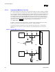
To allow for these high-speed data transfers, the 2× mode of AGP operation uses source-synchronous
data strobing. (Refer to Source-Synchronous Strobing section.) During 4× operation, the AGP interface
uses differential source-synchronous strobing.
With data cycle times as small as 3.75 ns and setup/hold times of 1 ns, the propagation delay mismatch is
critical. In addition to reducing propagation delay mismatch, it is important to minimize noise. Noise on
the data lines will cause the settling time to be long. If the mismatch between a data line and the
associated strobe is too great or if there is noise on the interface, incorrect data will be sampled.
The low-voltage operation on AGP (1.5 V) requires even more noise immunity. For example, during
1.5 V operation, V
ILMAX
is 570 mV. Without proper isolation, crosstalk could create signal integrity
issues.
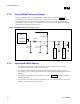
2.8.1. AGP Interface Signal Groups
The signals on the AGP interface are broken into three groups: 1× timing domain signals, 2×/4× timing
domain signals, and miscellaneous signals. Each group has different routing requirements. In addition,
within the 2×/4× timing domain signals, there are three sets of signals. All signals in the 2×/4× timing
domains must meet minimum and maximum trace length requirements as well as trace width and spacing
requirements. However, trace length matching requirements only must be met within each set of 2×/4×
timing domain signals.