
Personal Computer User Manual


Intel
®
820E Chipset
R
74 Design Guide
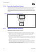
2.9. Hub Interface
The MCH and ICH2 ballout assignments have been optimized to simplify the hub interface routing
between these devices. It is recommended that the hub interface signals be routed directly from the MCH
to ICH2, with all signals referenced to V
SS
. Layer transition should be keep to a minimum. If a layer
change is required, use only two vias per net and keep all data signals and associated strobe signals on
the same layer. The hub interface is broken into two signal groups: data signals and strobe signals. These
groups are:
• Data signal
HL[10:0]
• Strobe signals
HL_STB
HL_STB#
Note: HL_STB/HL_STB# is a differential strobe pair.
For the 8-bit hub interface, HL[7:0] are associated with HL_STB and HL_STB#.
No pull-ups or pull-downs are required on the hub interface.
Each signal must be routed so as to meet the guidelines documented for the signal group to which it
belongs.
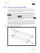
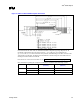
Figure 42. Hub Interface Signal Routing Example
ICH2 MCH
CLK synthesizer
HL_STB
HL_STB#
HL[10:0]
CLK66
CLK66
hub_sig_route