
Personal Computer User Manual


Intel
®
820E Chipset
R
76 Design Guide
Table 16. 8-Bit Hub Interface HUBREF Generation Circuit Specifications
Buffer Mode HUBREF Voltage Specification (V) Recommended Resistor Values
for the HUBREF Divider Circuit (
Ω
ΩΩ
Ω)
Normal/Single 1/2 V
CC
1_8 ± 2% R1 = R2 = 150 ± 1%
Normal/Local 2/3 V
CC
1_8 ± 2% R1 = 150 ± 1%, R2 = 301 ± 1%
The single HUBREF divider should not be located more than 4 inches away from either MCH or ICH2.
If the single HUBREF divider is located more than 4 inches away, then the locally generated hub
interface reference dividers should be used instead. The reference voltage generated by a single
HUBREF divider should be bypassed to ground at each component with a 0.0 µF capacitor located close
to the component HUBREF pin. If the reference voltage is generated locally, the bypass capacitor must
be close to the component HUBREF pin. Example HUBREF divider circuits are shown in the following
figures.
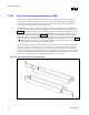
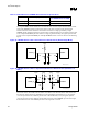
Figure 43. 8-Bit Hub Interface with a Shared Reference Divider Circuit (Normal/Single Mode)
HLREF_A
HUBREF
MCH
ICH2
hub_IF_ref_div_1
R1
1.8 V
R2
C2
C2
C1
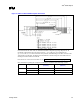
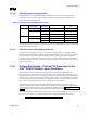
Figure 44. 8-Bit Hub Interface with Locally Generated Reference Divider Circuits (Normal/Local
Mode)
HLREF_A
HUBREF
MCH
ICH2
hub_IF_ref_div_2
1.8 V 1.8 V 1.8 V1.8 V
R2 R2
R1R1
C1
C1
C2 C2
The resistor values, R1 and R2, must be rated at 1% tolerance. The selected resistor values ensure that
the reference voltage tolerance is maintained over the input leakage specification. A 0.1 µF capacitor
(C1 in the previous circuits) should be placed close to R1 and R2. Also, a 0.01 µF bypass capacitor
(C2 in the previous circuits) should be placed within 0.25 inch of each HUBREF pin. The trace length
from the divider circuit to the HLREF pin must be no longer than 3.5 inches.