
user manual


Installations
14
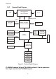
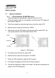
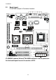
2.2 Board Layout
IP-4MTS6B Jumper & Connector Location
CN6
CN11
CN9
CN13
CN10
CN8
CN5
CN2
CN7
CN1
CN14
JP5
CN17
CN19
CN16
CN20
CN15
CN21
CN18
JP4
CN12
JP1JP2
CN4
93004
SYSTEM-FAN CPU-FAN
A
UTO POWER ON
EXT. KB/MS
KB/MS
COM1
VGA
USB0/1USB2/3
LAN1LAN2
LAN1-LED
LAN2-LED
IR-CONN
USB4/5
DIMM1
BATT1
LINE-OUT
CD-IN
IDE2
IDE1
FLOPPY
-PW LED LOCK PW ON
SPKR +HDLED RESET
LPT1
ECN RECORD
LVDS-CONN
COM2
CN3
JP6
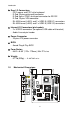
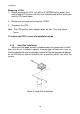
IP-4GMS6F onboard Celeron
®
M 600MHz without L2 cache processor.
So the board layout has not the socket of CPU.