
Datasheet

Technical Reference
57
affect the operation or throughput of the devices. In some special cases where maximum
performance is needed from a device, a PCI Conventional device should not share an interrupt with
other PCI Conventional devices. Use the following information to avoid sharing an interrupt with
a PCI Conventional add-in card.
PCI Conventional devices are categorized as follows to specify their interrupt grouping:
•
INTA: By default, all add-in cards that require only one interrupt are in this category. For
almost all cards that require more than one interrupt, the first interrupt on the card is also
classified as INTA.
•
INTB: Generally, the second interrupt on add-in cards that require two or more interrupts is
classified as INTB. (This is not an absolute requirement.)
•
INTC and INTD: Generally, a third interrupt on add-in cards is classified as INTC and a
fourth interrupt is classified as INTD.
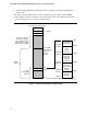
The ICH6 has eight Programmable Interrupt Request (PIRQ) input signals. All PCI Conventional
interrupt sources either onboard or from a PCI Conventional add-in card connect to one of these
PIRQ signals. Some PCI Conventional interrupt sources are electrically tied together on the board
and therefore share the same interrupt. Table 16 shows an example of how the PIRQ signals are
routed.
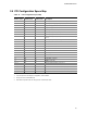
For example, using Table 16 as a reference, assume an add-in card using INTA is plugged into PCI
Conventional bus connector 3. In PCI bus connector 3, INTA is connected to PIRQB, which is
already connected to the ICH6 audio controller. The add-in card in PCI Conventional bus
connector 3 now shares an interrupt with the onboard interrupt source.
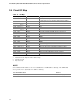
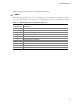
Table 16. PCI Interrupt Routing Map
ICH6 PIRQ Signal Name
PCI Interrupt Source
PIRQA PIRQB PIRQC PIRQD PIRQE PIRQF PIRQG PIRQH
IEEE1394a controller
(optional)
INTA
PCI bus connector 1 INTD INTA INTB INTC
PCI bus connector 2 INTC INTB INTA INTD
PCI bus connector 3
(Note)
INTD INTC INTA INTB
PCI bus connector 4
(Note)
INTB INTA INTC INTD
Note: Not present on the D915PCM board.
NOTE
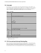
In PIC mode, the ICH6 can connect each PIRQ line internally to one of the IRQ signals (3, 4, 5, 6,
7, 9, 10, 11, 12, 14, and 15). Typically, a device that does not share a PIRQ line will have a
unique interrupt. However, in certain interrupt-constrained situations, it is possible for two or
more of the PIRQ lines to be connected to the same IRQ signal. Refer to Table 15 for the
allocation of PIRQ lines to IRQ signals in APIC mode.
PCI interrupt assignments to the USB ports, Serial ATA ports, and PCI Express ports are dynamic.