
Datasheet

Intel® Server Board S2600CW Connector/Header Locations and Pin-outs
Intel® Server Board S2600CW Family TPS
100 Revision1.11
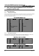
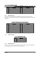
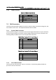
Table 19. Front Panel USB 3.0 Connector Pin-out
Pin Signal Name Pin Signal Name
1 P5V_AUX_USB_FP_USB3 key KEY
2 USB3_01_FB_RX_DN 19 P5V_AUX_USB_FP_USB3
3 USB3_01_FB_RX_DP 18 USB3_00_FB_RX_DN
4 GND 17 USB3_00_FB_RX_DP
5 USB3_01_FB_TX_DN 16 GND
6 USB3_01_FB_TX_DP 15 USB3_00_FB_TX_DN
7 GND 14 USB3_00_FB_TX_DP
8 USB2_13_FB_DN 13 GND
9 USB2_13_FB_DP 12 USB2_8_FB_DN
10 TP_FM_OC5_FP_R_N 11 USB2_8_FB_DP
7.3 On-board Storage Connectors
The server board provides connectors for support of several storage device options. This
section provides a functional overview and pin-out of each connector.
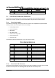
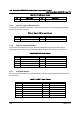
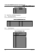
7.3.1 SATA 6Gbps Connectors
The server board includes two 7-pin SATA connectors capable of transfer rates of up to 6Gb/s.
The following table provides the pin-out for both connectors.
Table 20. SATA 6Gbps Connector Pin-out
Pin Signal Name
1 GND
2 SATA_TX_P
3 SATA_TX_N
4 GND
5 SATA_RX_N
6 SATA_RX_P
7 GND
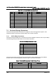
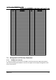
The server board also includes two mini-SAS HD ports, each supporting four SATA 6Gb/s
transfer rates. The following table provides the pin-out for both connectors.
Table 21. Mini-SAS HD Connectors for SATA 6Gbps Pin-out
Pin Signal Name Pin
Signal Name
1A1 TP_SAS1_BACKPLANE_TYPE 2A1
TP_SAS0_BACKPLANE_TYPE
1B1 GND 2B1 GND
1C1 SGPIO_SSATA_DATAOUT0_R1 2C1 SGPIO_SATA_DATAOUT0_R1