Intel® Desktop Board DG41AN Technical Product Specification June 2010 Order Number: E96323-001US The Intel® Desktop Board DG41AN may contain design defects or errors known as errata that may cause the product to deviate from published specifications. Current characterized errata are documented in the Intel Desktop Board DG41AN Specification Update.
Revision History Revision -001 Revision History Date ® First release of the Intel Desktop Board DG41AN Technical Product Specification June 2010 This product specification applies to only the standard Intel® Desktop Board DG41AN with BIOS identifier ANG4110H.86A. Changes to this specification will be published in the Intel Desktop Board DG41AN Specification Update before being incorporated into a revision of this document. INFORMATION IN THIS DOCUMENT IS PROVIDED IN CONNECTION WITH INTEL® PRODUCTS.
Preface This Technical Product Specification (TPS) specifies the board layout, components, connectors, power and environmental requirements, and the BIOS for the Intel® Desktop Board DG41AN. Intended Audience The TPS is intended to provide detailed, technical information about the Intel Desktop Board DG41AN and its components to the vendors, system integrators, and other engineers and technicians who need this level of information. It is specifically not intended for general audiences.
Intel Desktop Board DG41AN Technical Product Specification Other Common Notation iv # Used after a signal name to identify an active-low signal (such as USBP0#) GB Gigabyte (1,073,741,824 bytes) GB/s Gigabytes per second Gb/s Gigabits per second KB Kilobyte (1024 bytes) Kbit Kilobit (1024 bits) kbits/s 1000 bits per second MB Megabyte (1,048,576 bytes) MB/s Megabytes per second Mbit Megabit (1,048,576 bits) Mbits/s Megabits per second xxh An address or data value ending with a lowe
Contents 1 Product Description 1.1 Overview.......................................................................................... 9 1.1.1 Feature Summary .................................................................. 9 1.1.2 Board Layout ....................................................................... 11 1.1.3 Block Diagram ..................................................................... 13 1.2 Legacy Considerations......................................................................
2.5.1 Power Supply Considerations ................................................. 2.5.2 Fan Header Current Capability................................................ 2.5.3 Add-in Board Considerations .................................................. 2.6 Thermal Considerations .................................................................... 2.7 Reliability ....................................................................................... 2.8 Environmental .........................................
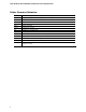
Contents Figures 1. 2. 3. 4. 5. 6. 7. 8. 9. 10. 11. 12. 13. 14. 15. Major Board Components.................................................................. 11 Block Diagram ................................................................................ 13 Memory Channel Configuration and DIMM Configuration........................ 18 Back Panel Audio Connectors ............................................................ 24 LAN Connector LED Locations .....................................................
29. 30. 31. 32. 33. 34. 35. 36. 37. 38. 39. 40. 41. 42. 43. viii Intel Desktop Board DG41AN Environmental Specifications .................... BIOS Setup Program Menu Bar.......................................................... BIOS Setup Program Function Keys.................................................... Acceptable Drives/Media Types for BIOS Recovery ............................... Boot Device Menu Options ................................................................
1 Product Description 1.1 Overview 1.1.1 Feature Summary Table 1 summarizes the major features of Intel® Desktop Board DG41AN. Table 1. Feature Summary Form Factor Mini-ITX (6.7 inches by 6.7 inches [170.18 millimeters by 170.
Intel Desktop Board DG41AN Technical Product Specification Table 1. Feature Summary (continued) Instantly Available PC Technology • Support for PCI* Local Bus Specification Revision 2.
Product Description 1.1.2 Board Layout Figure 1 shows the location of the major components. Figure 1. Major Board Components Table 2 lists the components identified in Figure 1.
Intel Desktop Board DG41AN Technical Product Specification Table 2.
Product Description 1.1.3 Block Diagram Figure 2 is a block diagram of the major functional areas. Figure 2.
Intel Desktop Board DG41AN Technical Product Specification 1.2 Legacy Considerations This board differs from other Intel® Desktop Board products, with specific changes including (but not limited to) the following: • • 1.3 No serial port on the back panel No diskette drive connector Online Support To find information about… Visit this World Wide Web site: Intel Desktop Board D425KT and Intel Desktop Board D425KTW http://www.intel.com/products/motherboard/index.htm Desktop Board Support http://www.
Product Description # INTEGRATOR’S NOTE Use only ATX12V-compliant power supplies. For information about Power supply connectors 1.5 Refer to Section 2.2.2.4, page 46 System Memory The board has two DIMM sockets and supports the following memory features: • • • 1.
Intel Desktop Board DG41AN Technical Product Specification The Desktop Board supports multiple processor and memory speeds. It is important to understand that not all memory speeds are supported with all processor speeds. Memory speed cannot exceed the Front Side Bus (FSB) speed of the processor. Table 3 lists the supported processor FSB and memory speeds. Table 3.
Product Description 1.5.1 Memory Configurations The Intel 82G41 GMCH supports the following types of memory organization: • • • Dual channel (Interleaved) mode. This mode offers the highest throughput for real world applications. Dual channel mode is enabled when the installed memory capacities of both DIMM channels are equal. Technology and device width can vary from one channel to the other but the installed memory capacity for each channel must be equal.
Intel Desktop Board DG41AN Technical Product Specification Figure 3 illustrates the memory channel and DIMM configuration. Figure 3. Memory Channel Configuration and DIMM Configuration # INTEGRATOR’S NOTE Regardless of the memory configuration used (dual channel, single channel, or flex mode), DIMM 0 of Channel A must always be populated.
Product Description Intel® G41 Express Chipset 1.6 The Intel G41 Express chipset consists of the following devices: • • Intel 82G41 Graphics and Memory Controller Hub (GMCH) with Direct Media Interface (DMI) interconnect Intel 82801GB I/O Controller Hub (ICH7) with DMI interconnect The GMCH component provides interfaces to the processor, memory, PCI, and the DMI interconnect. The component also provides integrated graphics capabilities supporting 3D, 2D, and display capabilities.
Intel Desktop Board DG41AN Technical Product Specification • Display ⎯ Supports digital and analog displays up to 2048 x 1536 at 75 Hz refresh (QXGA); also supports 1920 x 1080 resolution for full High Definition video playback quality ⎯ Dual independent display support 1.6.1.2 Dynamic Video Memory Technology (DVMT 5.0) DVMT enables enhanced graphics and memory performance through highly efficient memory utilization.
Product Description 1.6.2 USB The board supports up to eight USB 2.0 ports, supports UHCI and EHCI, and uses UHCI- and EHCI-compatible drivers. The ICH7 provides the USB controller for all ports.
Intel Desktop Board DG41AN Technical Product Specification 1.7 Real-Time Clock Subsystem A coin-cell battery (CR2032) powers the real-time clock and CMOS memory. When the computer is not plugged into a wall socket, the battery has an estimated life of three years. When the computer is plugged in, the standby current from the power supply extends the life of the battery. The clock is accurate to ± 13 minutes/year at 25 ºC with 3.3 VSB applied.
Product Description 1.8.2 PS/2 Keyboard/Mouse Interface The one PS/2 keyboard/mouse connector is located on the back panel. NOTE Power to the computer should be turned off before a keyboard is connected or disconnected. For information about Refer to The location of the keyboard/mouse connector Figure 9, page 41 1.
Intel Desktop Board DG41AN Technical Product Specification 1.9.1 Audio Subsystem Software Audio software and drivers are available from Intel’s World Wide Web site. For information about Refer to Obtaining audio software and drivers Section 1.3, page 14 1.9.2 Audio Connectors and Headers The board contains audio connectors on the back panel and audio headers on the component side of the board. The front panel audio header provides mic in and line out signals for the front panel.
Product Description 1.
Intel Desktop Board DG41AN Technical Product Specification 1.10.2 RJ-45 LAN Connector with Integrated LEDs Two LEDs are built into the RJ-45 LAN connector (shown in Figure 5). Item Description A Link LED (Green) B Data Rate LED (Green/Yellow) Figure 5. LAN Connector LED Locations Table 6 describes the LED states when the board is powered up and the LAN subsystem is operating. Table 6.
Product Description 1.11 Hardware Management Subsystem The hardware management features enable the board to be compatible with the Wired for Management (WfM) specification. The board has several hardware management features, including the following: • • • Fan monitoring and control Thermal and voltage monitoring Chassis intrusion detection 1.11.
Intel Desktop Board DG41AN Technical Product Specification 1.11.4 Thermal Monitoring Figure 6 shows the locations of the thermal sensors and fan headers. Item Description A Thermal diode, located on the processor die B Front chassis fan C Processor fan D Thermal diode, located on the GMCH die E Thermal diode, located on the ICH7 die Figure 6. Thermal Sensors and Fan Headers NOTE The minimum thermal reporting threshold for the GMCH is 66 °C.
Product Description 1.12 Power Management Power management is implemented at several levels, including: • • Software support through Advanced Configuration and Power Interface (ACPI) Hardware support: ⎯ Power connector ⎯ Fan headers ⎯ LAN wake capabilities ⎯ Instantly Available PC technology ⎯ Wake from USB ⎯ Wake from PS/2 device ⎯ Power Management Event signal (PME#) wake-up support ⎯ Wake from serial port 1.12.
Intel Desktop Board DG41AN Technical Product Specification 1.12.1.1 System States and Power States Under ACPI, the operating system directs all system and device power state transitions. The operating system puts devices in and out of low-power states based on user preferences and knowledge of how devices are being used by applications. Devices that are not being used can be turned off.
Product Description 1.12.1.2 Wake-up Devices and Events Table 9 lists the devices or specific events that can wake the computer from specific states. Table 9. Wake-up Devices and Events These devices/events can wake up the computer… …from this state LAN S1, S3, S4, S5 (Note) PME# signal S1, S3, S4, S5 (Note) Power switch S1, S3, S4, S5 PS/2 devices S1, S3, RTC alarm S1, S3, S4, S5 Serial port S1, S3 USB S1, S3 Note: S4 implies operating system support only.
Intel Desktop Board DG41AN Technical Product Specification 1.12.2 Hardware Support CAUTION Ensure that the power supply provides adequate +5 V standby current if LAN wake capabilities and Instantly Available PC technology features are used. Failure to do so can damage the power supply. The total amount of standby current required depends on the wake devices supported and manufacturing options.
Product Description 1.12.2.2 Fan Headers The function/operation of the fan headers is as follows: • • • • The fans are on when the board is in the S0 state. The fans are off when the board is off or in the S3, S4, or S5 state. The processor fan header is wired to a fan tachometer input. The front fan header has independent tachometer input to the hardware monitoring and fan control device. All fan headers support closed-loop fan control that can adjust the fan speed according to thermal conditions.
Intel Desktop Board DG41AN Technical Product Specification 1.12.2.4 Instantly Available PC Technology CAUTION For Instantly Available PC technology, the +5 V standby line from the power supply must be capable of providing adequate +5 V standby current. Failure to provide adequate standby current when implementing Instantly Available PC technology can damage the power supply. Instantly Available PC technology enables the board to enter the ACPI S3 (Suspend-toRAM) sleep-state.
Product Description 1.12.2.9 +5 V Standby Power Indicator LED The +5 V standby power indicator LED (green) shows that power is still present even when the computer appears to be off. Figure 7 shows the location of the standby power indicator LED. CAUTION If AC power has been switched off and the standby power indicator LED is still lit, disconnect the power cord before installing or removing any devices connected to the board. Failure to do so could damage the board and any attached devices. Figure 7.
Intel Desktop Board DG41AN Technical Product Specification 36
2 Technical Reference 2.1 Memory Map 2.1.1 Addressable Memory The board utilizes 4 GB of addressable system memory. Typically the address space that is allocated for Conventional PCI bus add-in cards, BIOS (SPI Flash), and chipset overhead resides above the top of DRAM (total system memory). On a system that has 4 GB of system memory installed, it is not possible to use all of the installed memory due to system address space being allocated for other system critical functions.
Intel Desktop Board DG41AN Technical Product Specification The amount of installed memory that can be used will vary based on add-in cards and BIOS settings. Figure 8 shows a schematic of the system memory map. All installed system memory can be used when there is no overlap of system addresses. Figure 8.
Technical Reference Table 10 lists the system memory map. Table 10. System Memory Map Address Range (decimal) Address Range (hex) Size Description 1024 K - 4194304 K 100000 - FFFFFFFF 4095 MB Extended memory 960 K - 1024 K F0000 - FFFFF 64 KB Runtime BIOS 896 K - 960 K E0000 - EFFFF 64 KB Reserved 800 K - 896 K C8000 - DFFFF 96 KB Potential available high DOS memory (open to the PCI bus). Dependent on video adapter used.
Intel Desktop Board DG41AN Technical Product Specification 2.2 Connectors and Headers CAUTION Only the following connectors and headers have overcurrent protection: Back panel and front panel USB and PS/2. The other internal connectors/headers are not overcurrent protected and should connect only to devices inside the computer’s chassis, such as fans and internal peripherals. Do not use these connectors/headers to power devices external to the computer’s chassis.
Technical Reference 2.2.1 Back Panel Connectors Figure 9 shows the locations of the back panel connectors. Item Description A PS/2 keyboard/mouse port B USB ports (2) C VGA port D Parallel port E DVI-D port F LAN G USB ports (2) H Line in I Mic in J Line out Figure 9.
Intel Desktop Board DG41AN Technical Product Specification 2.2.2 Component-side Connectors and Headers Figure 10 shows the locations of the component-side connectors and headers. Figure 10.
Technical Reference Table 11 lists the component-side connectors and headers identified in Figure 10. Table 11.
Intel Desktop Board DG41AN Technical Product Specification 2.2.2.1 Signal Tables for the Connectors and Headers Table 12. Serial ATA Connectors Pin Signal Name 1 Ground 2 TXP 3 TXN 4 Ground 5 RXN 6 RXP 7 Ground Table 13. Chassis Intrusion Header Pin Signal Name 1 Intruder 2 Ground Table 14. Serial Port Header Pin Signal Name Pin Signal Name 1 DCD 2 RXD# 3 TXD# 4 DTR 5 Ground 6 DSR 7 RTS 8 CTS 9 RI 10 Key (no pin) Table 15.
Technical Reference Table 17. Front Panel Audio Header for Intel® HD Audio Pin Signal Name Pin Signal Name 1 [Port 1] Left channel 2 Ground 3 [Port 1] Right channel 4 PRESENCE# (Dongle present) 5 [Port 2] Right channel 6 [Port 1] SENSE_RETURN 7 SENSE_SEND (Jack detection) 8 Key (no pin) 9 [Port 2] Left channel 10 [Port 2] SENSE_RETURN Table 18.
Intel Desktop Board DG41AN Technical Product Specification 2.2.2.4 Power Supply Connectors The board has the following power supply connectors: • • Main power – a 2 x 12 connector. This connector is compatible with 2 x 10 connectors previously used on Intel Desktop boards. The board supports the use of ATX12V power supplies with either 2 x 10 or 2 x 12 main power cables.
Technical Reference 2.2.2.5 Front Panel Header This section describes the functions of the front panel header. Table 22 lists the signal names of the front panel header. Figure 11 is a connection diagram for the front panel header. Table 22.
Intel Desktop Board DG41AN Technical Product Specification 2.2.2.5.2 Reset Switch Header Pins 5 and 7 can be connected to a momentary single pole, single throw (SPST) type switch that is normally open. When the switch is closed, the board resets and runs the POST. 2.2.2.5.3 Power/Sleep LED Header Pins 2 and 4 can be connected to a one- or two-color LED. Table 23 shows the possible states for a one-color LED. Table 24 shows the possible states for a two-color LED. Table 23.
Technical Reference 2.2.2.7 Front Panel USB Headers Figure 12 is a connection diagram for the front panel USB headers. # INTEGRATOR’S NOTES • • The +5 V DC power on the front panel USB headers is fused. Use only a front panel USB connector that conforms to the USB 2.0 specification for high-speed USB devices. Figure 12.
Intel Desktop Board DG41AN Technical Product Specification 2.3 Jumper Block CAUTION Do not move the jumper with the power on. Always turn off the power and unplug the power cord from the computer before changing a jumper setting. Otherwise, the board could be damaged. Figure 13 shows the location of the jumper block. The jumper determines the BIOS Setup program’s mode. Table 26 lists the jumper settings for the three modes: normal, configure, and recovery.
Technical Reference Table 26. BIOS Setup Configuration Jumper Settings Function/Mode Jumper Setting Configuration Normal 1-2 The BIOS uses current configuration information and passwords for booting. Configure 2-3 After the POST runs, Setup runs automatically. The maintenance menu is displayed. Recovery None The BIOS attempts to recover the BIOS configuration. See Section 3.7 for more information on BIOS recovery.
Intel Desktop Board DG41AN Technical Product Specification 2.4 2.4.1 Mechanical Considerations Form Factor The board is designed to fit into a Mini-ITX form-factor chassis. Figure 14 illustrates the mechanical form factor of the board. Dimensions are given in inches [millimeters]. The outer dimensions are 6.70 inches by 6.70 inches [170.18 millimeters by 170.18 millimeters]. Location of the I/O connectors and mounting holes are in compliance with the Mini-ITX specification.
Technical Reference 2.5 Electrical Considerations 2.5.1 Power Supply Considerations CAUTION The +5 V standby line from the power supply must be capable of providing adequate +5 V standby current. Failure to do so can damage the power supply. The total amount of standby current required depends on the wake devices supported and manufacturing options. Additional power required will depend on configurations chosen by the integrator.
Intel Desktop Board DG41AN Technical Product Specification 2.5.2 Fan Header Current Capability CAUTION The processor fan must be connected to the processor fan header, not to a chassis fan header. Connecting the processor fan to a chassis fan header may result in onboard component damage that will halt fan operation. Table 28 lists the current capability of the fan headers. Table 28. Fan Header Current Capability Fan Header Maximum Available Current Processor fan 2.0 A Front chassis fan 1.5 A 2.5.
Technical Reference Figure 15 shows the locations of the localized high temperature zones. Item Description A B C D Processor voltage regulator area Processor Intel 82G41 GMCH Intel 82801GB (ICH7) Figure 15.
Intel Desktop Board DG41AN Technical Product Specification Table 29 provides maximum case temperatures for the board components that are sensitive to thermal changes. The operating temperature, current load, or operating frequency could affect case temperatures. Maximum case temperatures are important when considering proper airflow to cool the board. Table 29. Thermal Considerations for Components 2.
Technical Reference 2.8 Environmental Table 30 lists the environmental specifications for the board. Table 30.
Intel Desktop Board DG41AN Technical Product Specification 58
3 Overview of BIOS Features 3.1 Introduction The board uses an Intel BIOS that is stored in the Serial Peripheral Interface Flash Memory (SPI Flash) and can be updated using a disk-based program. The SPI Flash contains the BIOS Setup program, POST, the PCI auto-configuration utility, and Plug and Play support. The BIOS displays a message during POST identifying the type of BIOS and a revision code. The initial production BIOSs are identified as ANG4110H.86A.
Intel Desktop Board DG41AN Technical Product Specification Table 31 lists the BIOS Setup program menu features. Table 31.
Overview of BIOS Features 3.4 System Management BIOS (SMBIOS) SMBIOS is a Desktop Management Interface (DMI) compliant method for managing computers in a managed network. The main component of SMBIOS is the Management Information Format (MIF) database, which contains information about the computing system and its components. Using SMBIOS, a system administrator can obtain the system types, capabilities, operational status, and installation dates for system components.
Intel Desktop Board DG41AN Technical Product Specification To install an operating system that supports USB, verify that Legacy USB support in the BIOS Setup program is set to Enabled and follow the operating system’s installation instructions. 3.6 BIOS Updates The BIOS can be updated using either of the following utilities, which are available on the Intel World Wide Web site: • • • Intel® Express BIOS Update utility, which enables automated updating while in the Windows environment.
Overview of BIOS Features 3.6.2 Custom Splash Screen During POST, an Intel® splash screen is displayed by default. This splash screen can be augmented with a custom splash screen. The Intel Integrator Toolkit or Intel® Integrator Assistant that are available from Intel can be used to create a custom splash screen. NOTE If you add a custom splash screen, it will share space with the Intel branded logo. For information about Refer to Intel Integrator Toolkit http://developer.intel.
Intel Desktop Board DG41AN Technical Product Specification 3.8 Boot Options In the BIOS Setup program, the user can choose to boot from a hard drive, optical drive, removable drive, or the network. The default setting is for the optical drive to be the first boot device, the hard drive second, removable drive third, and the network fourth. 3.8.1 Optical Drive Boot Booting from the optical drive is supported in compliance to the El Torito bootable CD-ROM format specification.
Overview of BIOS Features 3.9 Adjusting Boot Speed These factors affect system boot speed: • • 3.9.1 Selecting and configuring peripherals properly Optimized BIOS boot parameters Peripheral Selection and Configuration The following techniques help improve system boot speed: • • • • 3.9.2 Choose a hard drive with parameters, such as “power-up to data ready” in less than eight seconds, that minimize hard drive startup delays. Select an optical drive with a fast initialization rate.
Intel Desktop Board DG41AN Technical Product Specification 3.10 BIOS Security Features The BIOS includes security features that restrict access to the BIOS Setup program and who can boot the computer. A supervisor password and a user password can be set for the BIOS Setup program and for booting the computer, with the following restrictions: • • • • • • • The supervisor password gives unrestricted access to view and change all the Setup options in the BIOS Setup program. This is the supervisor mode.
4 Error Messages and Beep Codes 4.1 Speaker The board-mounted speaker provides audible error code (beep code) information during POST. 4.2 For information about Refer to The location of the onboard speaker Figure 1, page 11 BIOS Beep Codes Whenever a recoverable error occurs during POST, the BIOS causes the board’s speaker to beep an error message describing the problem (see Table 36). Table 36. BIOS Beep Codes Type Pattern Frequency Processor initialization complete One 0.
Intel Desktop Board DG41AN Technical Product Specification 4.3 Front-panel Power LED Blink Codes Whenever a recoverable error occurs during POST, the BIOS causes the board’s front panel power LED to blink an error message describing the problem (see Table 37). Table 37. Front-panel Power LED Blink Codes 4.4 Type Pattern Note Processor initialization complete On when the system powers up, then off for 0.5 seconds. POST complete On when the system powers up, then off for 0.5 seconds.
Error Messages and Beep Codes 4.5 Port 80h POST Codes During the POST, the BIOS generates diagnostic progress codes (POST codes) to I/O port 80h. If the POST fails, execution stops and the last POST code generated is left at port 80h. This code is useful for determining the point where an error occurred. Displaying the POST codes requires a PCI bus add-in card, often called a POST card. The POST card can decode the port and display the contents on a medium such as a seven-segment display.
Intel Desktop Board DG41AN Technical Product Specification Table 40.
Error Messages and Beep Codes Table 40.
Intel Desktop Board DG41AN Technical Product Specification Table 40.
Error Messages and Beep Codes Table 41.
Intel Desktop Board DG41AN Technical Product Specification 74
5 Regulatory Compliance and Battery Disposal Information 5.1 Regulatory Compliance This section contains the following regulatory compliance information for Intel Desktop Board DG41AN: • • • • • 5.1.
Intel Desktop Board DG41AN Technical Product Specification 5.1.2 European Union Declaration of Conformity Statement We, Intel Corporation, declare under our sole responsibility that the product Intel® Desktop Board DG41AN is in conformity with all applicable essential requirements necessary for CE marking, following the provisions of the European Council Directive 2004/108/EC (EMC Directive), 2006/95/EC (Low Voltage Directive), and 2002/95/EC (ROHS Directive).
Regulatory Compliance and Battery Disposal Information Portuguese Este produto cumpre com as normas da Diretiva Européia 2004/108/EC, 2006/95/EC & 2002/95/EC. Español Este producto cumple con las normas del Directivo Europeo 2004/108/EC, 2006/95/EC & 2002/95/EC. Slovensky Tento produkt je v súlade s ustanoveniami európskych direktív 2004/108/EC, 2006/95/EC a 2002/95/EC. Slovenščina Izdelek je skladen z določbami evropskih direktiv 2004/108/EC, 2006/95/EC in 2002/95/EC.
Intel Desktop Board DG41AN Technical Product Specification Español Como parte de su compromiso de responsabilidad medioambiental, Intel ha implantado el programa de reciclaje de productos Intel, que permite que los consumidores al detalle de los productos Intel devuelvan los productos usados en los lugares seleccionados para su correspondiente reciclado. Consulte la http://www.intel.
Regulatory Compliance and Battery Disposal Information Russian В качестве части своих обязательств к окружающей среде, в Intel создана программа утилизации продукции Intel (Product Recycling Program) для предоставления конечным пользователям марок продукции Intel возможности возврата используемой продукции в специализированные пункты для должной утилизации. Пожалуйста, обратитесь на веб-сайт http://www.intel.
Intel Desktop Board DG41AN Technical Product Specification FCC Declaration of Conformity This device complies with Part 15 of the FCC Rules. Operation is subject to the following two conditions: (1) this device may not cause harmful interference, and (2) this device must accept any interference received, including interference that may cause undesired operation. For questions related to the EMC performance of this product, contact: Intel Corporation, 5200 N.E.
Regulatory Compliance and Battery Disposal Information Japan VCCI Statement Japan VCCI Statement translation: This is a Class B product based on the standard of the Voluntary Control Council for Interference from Information Technology Equipment (VCCI). If this is used near a radio or television receiver in a domestic environment, it may cause radio interference. Install and use the equipment according to the instruction manual.
Intel Desktop Board DG41AN Technical Product Specification 5.1.5 ENERGY STAR* 5.0, e-Standby, and ErP Compliance The US Department of Energy and the US Environmental Protection Agency have continually revised the ENERGY STAR requirements. Intel has worked directly with these two governmental agencies in the definition of new requirements.
Regulatory Compliance and Battery Disposal Information 5.1.6 Regulatory Compliance Marks (Board Level) Intel Desktop Board DG41AN has the regulatory compliance marks shown in Table 44. Table 44. Regulatory Compliance Marks Description Mark UL joint US/Canada Recognized Component mark. Includes adjacent UL file number for Intel Desktop Boards: E210882. FCC Declaration of Conformity logo mark for Class B equipment. CE mark.
Intel Desktop Board DG41AN Technical Product Specification 5.2 Battery Disposal Information CAUTION Risk of explosion if the battery is replaced with an incorrect type. Batteries should be recycled where possible. Disposal of used batteries must be in accordance with local environmental regulations. PRÉCAUTION Risque d'explosion si la pile usagée est remplacée par une pile de type incorrect. Les piles usagées doivent être recyclées dans la mesure du possible.
Regulatory Compliance and Battery Disposal Information PRECAUCIÓN Existe peligro de explosión si la pila no se cambia de forma adecuada. Utilice solamente pilas iguales o del mismo tipo que las recomendadas por el fabricante del equipo. Para deshacerse de las pilas usadas, siga igualmente las instrucciones del fabricante. WAARSCHUWING Er bestaat ontploffingsgevaar als de batterij wordt vervangen door een onjuist type batterij. Batterijen moeten zoveel mogelijk worden gerecycled.
Intel Desktop Board DG41AN Technical Product Specification AWAS Risiko letupan wujud jika bateri digantikan dengan jenis yang tidak betul. Bateri sepatutnya dikitar semula jika boleh. Pelupusan bateri terpakai mestilah mematuhi peraturan alam sekitar tempatan. OSTRZEŻENIE Istnieje niebezpieczeństwo wybuchu w przypadku zastosowania niewłaściwego typu baterii. Zużyte baterie należy w miarę możliwości utylizować zgodnie z odpowiednimi przepisami ochrony środowiska.
Regulatory Compliance and Battery Disposal Information 87
Intel Desktop Board DG41AN Technical Product Specification 88