
Accelerated Graphics Port Interface Specification


AGP3.0 Interface Specification
Rev. 1.0
105
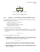
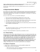
AGP8X
fanout
Bridge
AGP8X port
Device
Device
Target
AGP/AGP8X port
AGP/AGP8X port
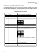
Figure 4-3: AGP3.0 Fanout Bridge Connections
4.1.10 Setting T, L, Y, N for AGP3.0 Core-logic and AGP3.0 Devices
Several isochronous parameters must be set to compatible values on the AGP3.0 core-logic (target)
and the AGP3.0 Master device(s), including:
• Isochronous time period (T = 1 microsecond)
• Isochronous Data Payload size (Y)
• Number of isochronous transactions per period (N)
• Isochronous request queue size (Q),
These parameters must be setup in the following order.
1. The AGP3.0 core-logic advertises its default isochronous data payload size (Y
core-logic
), which may
be adjusted upward, if necessary, to agree with the AGP3.0 Master device’s isochronous payload
size (Y
device
).
)
devicechipset
,Y
Max(Y
Y
=
2. Isochronous bandwidth is allocated in two steps:
A. Data Bandwidth: The sum of AGP3.0 Master device transaction allocations must be less than
or equal to the AGP3.0 core-logic’s transaction capability (N
core-logic
). The transaction capability
may depend on the AGP3.0 core-logic’s isochronous transaction size.
2
NNN
chipset
+≥
1
In the above equation N
1
and N
2
represent the isochronous transactions per time period T
required by a one or more AGP3.0 devices. These include both read and write transactions.
B. Request Bandwidth: An AGP3.0 core-logic must specify a maximum request queue capability
between 1 and 256. AGP3.0 Master device(s) must make sure the AGP3.0 target’s request
queue is never overfilled.