
Accelerated Graphics Port Interface Specification


AGP3.0 Interface Specification
Rev. 1.0
111
4.3.5 Synchronization Scheme: Case 2 AGP Data to Processor
The following scheme ensures correct operation.
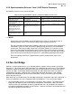
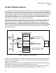
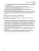
Table 53: The Synchronization Sequence of Data from AGP to the Processor
AGP3.0 Device Actions Core-logic Actions Processor Actions
Writes to memory (Could be low
priority Async. or Isoch).
Writes may complete in any order in
system memory.
Processor polls flag to set. (Optionally waits for signal
to poll).
Executes a Fence for
Asynchronous Writes (skip step
for Isoch Writes).
Core-logic inserts Fence in low
priority write queue to ensure order.
Processor polls flag to set (Optionally waits for signal
to poll).
Writes flag in system memory to
indicate completion. For Isoch
writes this will be an Isoch
Write/Fenced. This system
memory is likely to be in non-
snoop space.
Core-logic will guarantee that this
write will complete following previous
writes.
Processor polls flag to set (Optionally waits for signal
to poll).
Optionally signals processor to
poll flag (interrupt or cached
write).
Core-logic delivers this signal if
needed.
Processor finds flag set and proceeds to read AGP3.0
data.
/ NOTE
Asynchronous and Isoch Writes may be completed in any order. It is essential to insert an
ordering operation such as a Fence before setting a flag to signal the processor.
The write of the flag to indicate buffer availability is likely to be in un-cached space especially for
Isoch Writes. If this is the case, the processor polling the flag generates a lot of undesirable
system traffic. There are probably several ways around this problem. One of these is for the
processor to not poll the flag until another signal is received. This signal could be an interrupt
(from an AGP3.0 device or a periodic system event) or a setting of a secondary flag in cached
space, which may be polled locally in the processor’s cache without generating system traffic.
The exact signaling mechanism is implementation specific and beyond the scope of this
specification.
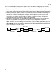
4.4 Fan-Out Bridge
AGP3.0 is a point-to-point interface, necessitated by both the signaling scheme and the speed of the
data transfer. This means that an AGP3.0 interface can support only one device slot. A Fan-out Bridge
component could be designed to interconnect more than one AGP3.0 device to a single AGP3.0 port
from the core-logic. Such a bridge would be located on the motherboard side, which, from a device
configuration perspective, is different from a similar bridge located on the graphics card. A bridge
located on the motherboard needs to ensure that it behaves exactly as the Core-Logic to any AGP
device that connects to it.
While the design specification of the Fan-out Bridge component is beyond the scope of this document, a
few basic requirements for such a component will be described here. These are listed as follows.
• The Fan-out Bridge features are required to be “transparent” to the software. This implies that the
bridge does not require any PCI enumeration or configuration. Furthermore, it does not contain
software-visible (OS, applications or drivers) programmable state. An exception to this might be a
level of BIOS initialization of platform specific features. However, the AGP3.0 specification does not
describe any platform specific features.