
Accelerated Graphics Port Interface Specification

AGP3.0 Interface Specification
Rev. 1.0
123
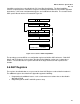
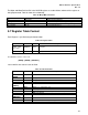
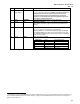
Capabilities mechanism as described in the PCI Local Bus Specification. The New Capabilities
structure is implemented as a linked list of registers containing information for each function supported
by the device. AGP status and Command registers are included in the linked list. The structure for the
AGP specific ID and structure is illustrated in Figure 5-3.
1
Status
AGP Status Register
AGP Command Register
ID=TBD
34h
08h
Command
Minor
Major
Capability Registers
(last device)
NULL
ID
Capability Pointer
Bit 4
AGP Register
AGP Register
Figure 5-3: Location of AGP3.0 Capabilities
The operating system and BIOS use configuration registers to initialize AGP3.0 features. Both AGP
Master and Target devices in the registers described in the following sections must support these
features. The text describes the specific behavior of the target and master with respect to each
function.
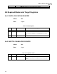
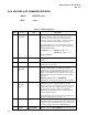
5.6 AGP Registers
The registers described below are a superset of the Core AGP Register set described in Section 2.5.
The additional registers described in this Appendix support the following:
1. Programming for additional features such as isochronous transactions that are described in
Appendix A and B.
2. Programming for the GART and AGP aperture setup.