
Accelerated Graphics Port Interface Specification

AGP3.0 Interface Specification
Rev. 1.0
19
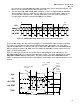
may start at any rising SB_STBF edge within a common clock cycle at the AGP3.0 Master. The
Master must insert NOPs into any unused request slots.
3. The two strobes SB_STBF and SB_STBS alternately use the L->H edge to latch the SBA data.
The illustration in Figure 2-1 shows the one strobe as the inverse of the other. However, the
specification does not require this. The only requirement is for each strobe to provide an
assertion edge centered in each alternate SBA transfer window.
CLK
1
2
3
SBA#[7::0]
SB_STBS
SB_STBF
8-6a
T1H
T3H
NOP
T3L
T3L
T2L
T2H
NOP
NOP
NOP
T1L
NOP
NOP
T1L
T1H
NOP
NOP
T3H
Figure 2-1: 8X SBA Addressing Showing Three Consecutive SBA Requests
To restart SBA strobes after they have been stopped, a synchronization sequence must be followed.
This sequence is based on the AGP Interface Specification and is described in Sec 3.2.2. When
stopped, the SBA Strobes are both in LOW state. In AGP2.0 the SBA Strobes are treated differentially.
When restarting the strobes, SB_STBF starts first followed by SB_STBS. For either strobe, the rising
edge is used for latching data.
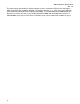
Figure 2-2 and Figure 2-3 illustrate the 8X data transfer timing diagram on the AD interface. The
AD_STBF and AD_STBS are used to latch the data at the receiver. As in AGP, CLK based PCI signals
GNT, TRDY and IRDY control the flow of data. The timing relationship between IRDY/TRDY and the
strobes is designed specifically to transfer data from the strobe latches to the CLK based latches in the
receiver.
Figure 2-2: 8X Data Transfers on AD Interface
CLK
1
2
3
AD
AD_STBS
AD_STBF
TRDY
Data in
Master’
Common
Clock
Domain
In Cycle 3
.
1
6 5
8
2
3
4
7
First Data Latched
in receiver
Last
th
) Data
Latched in
her
t
1max
t
2m
ax
t
3min