
Accelerated Graphics Port Interface Specification

AGP3.0 Interface Specification
Rev. 1.0
21
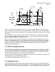
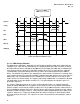
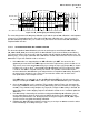
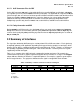
Figure 2-3: Minimum TRDY and AD_STB Timing Relationship
Figure 2-3 shows the minimum delay between common clock and AD_STB (and the corresponding
data). The delay t
1min
represents the earliest the first data is latched into the receiver using the strobe.
The delay t
2min
represents the earliest the last of the eight pieces of data per common clock is latched in
the receiver.
The time period t
3max
represents the setup time to the next common clock edge to transfer the eight
pieces of data to the common clock domain. In this case, there is plenty of setup time, and the data
appears to precede TRDY by a considerable amount.
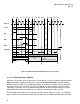
Figure 2-2 illustrates a case where the delay between common clock and the AD_STB is the greatest.
However, even with this delay, t
3min
is still sufficient to meet the setup time of the common clock edge
for cycle 3. Nothing has changed between the two cases in regards to the common clock’s domain.
However, data in this case appears to be lagging behind TRDY by a considerable margin, however,
according to the timing diagrams.
2.1.3 AGP3.0 Signaling Scheme
The AGP3.0 interface is point-to-point, the same as AGP2.0. All signals that use the AGP3.0 signaling
scheme are parallel terminated to Vss (signal reference) on both ends with a termination value of the
interconnection trace impedance. The termination is provided on-chip with an implementation specific
scheme to closely match the value to interconnect trace impedance.
Only the 8X signals need to adopt the new signaling to sustain the increased frequency, although the 1X
signals will also use the same signaling scheme.
The 66 MHz CLK and RST# signals continue to be 3.3 V.
2.1.4 Calibration Cycle
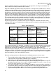
The AGP3.0 signaling scheme requires tight control over variation in the key specification parameters:
on-die termination impedance, signal swing, and slew rate. The key variables of process, voltage, and
temperature cause the variations in these parameters. To maintain control over the variations, static or
CL
1
2
3
A
AD_STB
AD_STB
TRD
Data
Master’
Commo
Cloc
Domai
In Cycle 3
.
1
6
5
2
3
4
7
First Data
in receiver
Last
th
) Data
Latched in
her
t
1min
t
2
min
t
3max