
Accelerated Graphics Port Interface Specification


AGP3.0 Interface Specification
Rev. 1.0
24
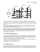
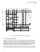
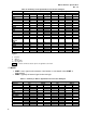
Figure 2-4: AGP3.0 Calibration Cycle
2.1.4.1 SBA Group Calibration
The SBA interface calibration is initiated by the AGP3.0 Master (Graphics Chip) and is triggered by the
calibration cycle. Soon after the calibration cycle is completed (IRDY and TRDY have been asserted),
the AGP3.0 Master initiates calibration of the SBA interface by stopping the SBA strobes and driving the
entire interface low for a minimum of eight AGP common clock cycles (as required by the sideband
synchronization specification) during which time it performs the needed adjustments to its SBA I/O
buffers. The AGP3.0 Target detects the stopping of the strobes within a maximum of six common clock
cycles and then performs the required termination calibration within two common clock cycles while the
SBA activity is still suspended by the master. Following this, the AGP3.0 Master can restart the SBA
strobes and resume normal activity. The stopping and starting of SBA strobes must follow the sideband
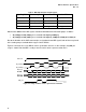
synchronization scheme described in Section 3.2.2. The timing diagram describing this process is
illustrated in Figure 2-5.
The Target is allowed a maximum of six cycles to detect that the strobes are stopped. During this
period, the Master must not cause any glitches on the strobe lines due to any compensation updates.
After this period is over the Master continues to drive NOPs on the SBA and keep the strobes low for at
least two additional common clock cycles. Both the Master and Target may perform the buffer updates
during this period. If the Master chooses, it may extend the update period by delaying the strobe restart
sequence. However, the Target may not depend on this and must complete its buffer updates within
these two common clock cycles. The sequence of events is illustrated in the timing diagram shown in
Figure 2-5.
AGP CLK
ST[2:0]
GNT
IRDY
TRDY
AD[31:0]
C#/BE[3:0]
11
000
Next
T1 T2 T3 T4 T5
Delayed 1
Earliest that IRDY or
TRDY can be asserted