
Accelerated Graphics Port Interface Specification


AGP3.0 Interface Specification
Rev. 1.0
28
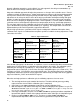
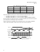
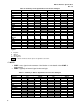
Table 8: DBI Implementation Requirements
Signaling Mode Transfer Speed Transmitter DBI Receiver DBI
AGP V3.0 8X Required Required
AGP V3.0 4X Optional Required
AGP V3.0 Frame Based PCI
Optional Required
AGP 1.0 or 2.0 Any Not Supported Not Supported
Note that the addition of the DBI signals extends the definition of the AD strobe groups as follows:
• AD_STBF[0] and AD_STBS[0] are associated with AD[15:0], C#/BE[1:0]
• AD_STBF[1] and AD_STBS[1] are associated with AD[31:16], C#/BE[3:2] and DBI_HI and DBI_LO
Due to the locations of the AGP connector pins assigned to the two DBI signals, both of them are placed
in the strobe group associated with the upper sixteen AD bits.
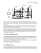
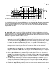
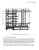
Figure 2-7 illustrates the use of DBI on source synchronous transfers. In this example, only DBI_LO
usage is shown. Note that DBI is used per transfer and is not on a per transaction basis.
AD_STBS[0]
AD[15:0]
No DBI
000F
FF00
001F
AD_STBF[0]
FF00
1100
FFFF
FF00
0000
AGP CLK
AD[15:0]
With DBI
DBI_LO
000F
00FF
001F
00FF
EEFF
FFFF
FF00
0000
Figure 2-7: Usage of DBI on Source Synchronous Transfers