
Accelerated Graphics Port Interface Specification


AGP3.0 Interface Specification
Rev. 1.0
50
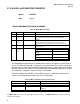
2.8 AGP3.0 Connector Pin-outs
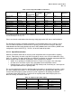
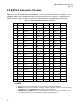
Both Universal AGP3.0 and AGP3.0 motherboards use the same AGP connectors as AGP2.0. A few
additional signals have been defined to take the place of previously reserved pins. Furthermore, the
polarity of certain signals is different from AGP. Table 29 contains the updated pin assignments.
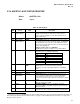
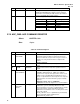
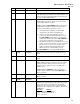
Table 29: AGP3.0 Motherboard Connector Pinout
Pin#
B A Pin#
B A Pin#
B A
1 OVRCNT# 12V 23 GND GND 45 KEY KEY
2 5.0V TYPEDET# 24 3.3V AUX Reserved 46 DEVSEL TRDY
3 5.0V GC_DET# 25 VCC3.3 VCC3.3 47 Vddq1.5 STOP
4 USB+ USB- 26 AD31 AD30 48 PERR PME#
5 GND GND 27 AD29 AD28 49 GND GND
6 INTB# INTA# 28 VCC3.3 VCC3.3 50 SERR PAR
7 CLK RST# 29 AD27 AD26 51 C#/BE1 AD15
8 REQ GNT 30 AD25 AD24 52 Vddq1.5 Vddq1.5
9 VCC3.3 VCC3.3 31 GND GND 53 AD14 AD13
10 ST0 ST1 32 AD_STBF1 AD_STBS1 54 AD12 AD11
11 ST2 MB _DET# 33 AD23 C#/BE3 55 GND GND
12 RBF DBI_HI 34 Vddq1.5 Vddq1.5 56 AD10 AD9
13 GND GND 35 AD21 AD22 57 AD8 C#/BE0
14 DBI_LO WBF 36 AD19 AD20 58 Vddq1.5 Vddq1.5
15 SBA0# SBA1# 37 GND GND 59 AD_STBF0 AD_STBS0
16 VCC3.3 VCC3.3 38 AD17 AD18 60 AD7 AD6
17 SBA2# SBA3# 39 C#/BE2 AD16 61 GND GND
18 SB_STBF SB_STBS 40 Vddq1.5 Vddq1.5 62 AD5 AD4
19 GND GND 41 IRDY FRAME 63 AD3 AD2
20 SBA4# SBA5# 42 KEY KEY 64 Vddq1.5 Vddq1.5
21 SBA6# SBA7# 43 KEY KEY 65 AD1 AD0
22 Reserved Reserved 44 KEY KEY 66 AGPVrefcg AGPVrefgc
/ NOTE
1. Reserved pins are only for future use by the AGP3.0 interface specification.
2. IDSEL# is not a pin on the AGP3.0 connector. AGP3.0 graphics components should connect
the AD16 signal to the IDSEL# function internal to the component.
3. TYPEDET# & GC_DET# should be both grounded by AGP3.0 and Universal AGP3.0 cards.
These will be pulled up to the appropriate voltage by the motherboard.