
Accelerated Graphics Port Interface Specification

AGP3.0 Interface Specification
Rev. 1.0
59
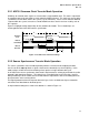
Due to this uncertainty window as to when the first edge of AD_STBF will be sent, the earliest safe
receiver transfer point from the inner to the outer loops occurs at the end of T2. The minimum
specification scenario implies that a second set of AD_STBF/AD_STBS strobes occurs in T2, when a
second set of eight DWords of data is being transferred.
Therefore, to prevent data from being overwritten before the safe transfer point, at least eight stages of
latches, for each strobe, must exist in the receiver inner loop input circuitry (i.e., at least two common
clock periods of data must be buffered).
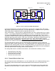
The latched data will be transferred to the outer loop into an edge-triggered latch driven by the common
clock. The inner loop latched data must be guaranteed to remain stable at the point of transfer, (i.e., on
the rising edge of the common clock).
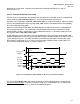
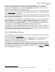
The minimum setup specification on the receive AD_STBS to clock (T
RS8su
) exists to ensure that data
from the output of an inner loop latch has a defined setup time to the input of the outer loop’s latch.
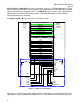
Figure 3-6 highlighted T
RS8su
(Figure 3-4highlights the transmit side equivalent, T
TS8r
). Likewise, the
minimum hold spec on the AD_STBF/AD_STBS (T
RS8h
) exists to ensure that data from the output of an
inner loop latch has a defined hold time relative to the input of the outer loop’s latch.
As with AGP2.0, the receive AD_STBF/AD_STBS strobe specification values were chosen to allow most
implementations to transfer data at the earliest safe point, or at the end of T2. However, the actual
transfer point is not specified, only the earliest viable point. An implementation may elect to increase the
effective setup time through additional buffering of the inner loop.
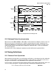
3.2.2.4 Transmit Outer to Inner Loop
This section addresses the timing relationship between the outer loop (common clock) and inner loop
(8X source synchronous) at the transmitter.
These timings are required to create a deterministic relationship between the inner loop data transfer
and the associated outer loop flow control events (i.e., FRAME, TRDY). These AGP3.0 timing
relationships are very similar to those of AGP2.0.
16
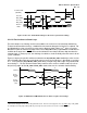
As with AGP2.0, to guarantee a deterministic relationship between the inner loop data transfer and the
corresponding outer loop flow control within the 8X mode, the first AD_STBF rising edge is required to
occur within the T1 clock period, as seen at the receiver. Proper timings are managed by a minimum
specification from the common clock to first AD_STBF rising edge (T
TSf
) and a maximum specification
for the last AD_STBS rising edge (T
TS8r
).
16
AGP2.0 defines a parameter termed t
TS4R
that logically equates to t
TS8R
for AGP3.0.