
Accelerated Graphics Port Interface Specification

AGP3.0 Interface Specification
Rev. 1.0
66
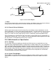
Care must be taken to avoid coupling to any high frequency signals that might cause EMI radiation
problems when a cable is attached. Associated power lines should be properly bypassed to decouple
noise.
INTA#, INTB#, and PME# are all 3.3 V open drain signals driven by the AGP Master, referenced to the
VCC3.3 power supply. These interrupt and power management signals subsequently may be
interfaced to +5 V PCI devices on the motherboard. It is a requirement of the motherboard designer to
properly interface the AGP interrupts to the PCI bus. This can be done in several ways. One option is
to pull up the PCI interrupts to 3.3 V only, allowing the AGP interrupts to connect directly to the PCI
interrupts. Alternatively, the AGP interrupts can be buffered to the PCI bus, thus isolating the 5V
environment from the AGP interconnect.
CLK and RST# are also 3.3 V signals which may require that special controller input circuitry be
supplied, or dividers provided in the receiver or on the platform, to prevent over-voltage or signal
distortion at the pin.
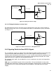
3.5 System Topologies and Specifications
As with AGP2.0, the AGP3.0 interface is a logical point-to-point
20
network. The AC timings and electrical
loading on the AGP3.0 interface are optimized for one active host component on the motherboard and
one active AGP3.0 agent. More than two physical connections to the interconnect are not
recommended since there is little timing margin for the added load, stubs and other signaling
discontinuities. If the interconnect is comprised of more than two loads and/or branching in the
topology, it is the system designer’s responsibility to ensure compliance to this interface specification.
Interconnect and package requirements are explicitly called out in subsequent sections of this
specification for the topologies listed later. This specification takes into consideration many concerns
including different design cost constraints. For example, lower cost solutions can choose to utilize
microstrip interconnect technology over symmetric stripline.
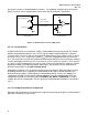
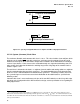
3.5.1 Universal AGP3.0 Topologies
The “Universal” topology (Universal AGP3.0) anticipates a host component that resides directly on the
motherboard or that is possibly connected through an AGP connector to an AGP2.0, AGP3.0 or
Universal AGP3.0 device.
Associated transmission line routing must meet both AGP2.0 and Universal AGP3.0 routing rules.
Routing for AGP3.0 also supports AGP2.0, except that AGP3.0 can support longer stripline trace
lengths. AGP3.0 interconnects must be referenced to ground to preserve noise margin. Universal
topologies are limited to source synchronous interconnects with a flight time of 2.1 ns. It is expected
that most early AGP3.0 designs will target the Universal AGP3.0 topology requirements.
Section 3.5.6 outlines the motherboard and add-in card interoperability options for Universal AGP3.0,
AGP3.0, and AGP2.0. For all of the topologies the V
DDQ
signal is required to be 1.5 V.
20
This means that active communication can only occur between two AGP3.0 agents that reside on the interface, where one
agent is referred to as the AGP3.0 target and the other the AGP3.0 Master. The simplest implementation is to have only two
devices attached to the bus. The specification does not preclude attaching more than two devices to the interface as long
as there is only one active master and one active target. Any other device must not respond to or interfere with the interface
operation. More than two devices are not recommended. When more than two devices are attached to the interface, the
system designer is responsible to ensure that all requirements of this interface specification are met; since the component
and/or add-in card designer has no control on how the devices are used.