
Accelerated Graphics Port Interface Specification


AGP3.0 Interface Specification
Rev. 1.0
67
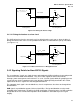
3.5.2 Other Topologies
It is possible to design a system with master and target devices both “down” on the motherboard,
without an intervening connector. Also, custom systems with a connector other than the standard AGP
connector can be built. Both of these cases can benefit from these specifications, however this
specification is not meant to cover or constrain either of these configurations.
3.5.3 System Level Definitions
3.5.3.1 Interconnect Layout Definitions
Interconnect layout strongly influences its effective impedance; “effective impedance” incorporates all
coupling effects including crosstalk. Furthermore, the sensitivity of effective impedance to simultaneous
switching (its magnitude and direction) of nearby AGP3.0 traces is greatly influenced by the relationship
of these traces to their coupled power and ground/reference planes.
Minimum and/or maximum “Effective Impedance” represents worst (corner) impedance cases
generated under corner conditions for all parameters that influence impedance such us: effective
dielectric constant (e
r
), maximum/minimum stackup tolerances, even/odd switching modes etc.
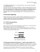
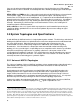
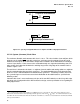
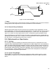
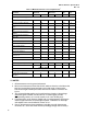
AGP3.0 requires that the traces be strongly coupled to ground. Stripline
21
and microstrip styled board
implementations are shown in the figures that follow. Space and height definitions for Table 33 and
Table 34 are shown in Figure 3-12.
21
Symmetric stripline is defined as H = H’.