
Accelerated Graphics Port Interface Specification

AGP3.0 Interface Specification
Rev. 1.0
70
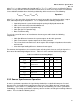
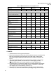
Table 33 Motherboard Interconnect Requirements
1
Parameter AGP3.0-DT AGP3.0-WS Units Notes
Min Max Min Max
Source Synchronous Signals
Interconnect Length - Stripline 2.0 7.0 inches 2
Interconnect Length - Microstrip 2.0 6.00 inches 2
Interconnect Mismatch – strobe-to-
strobe
5 5 mils 3
Interconnect Mismatch – strobe-to-
data
25 25 mils 3
Trace Characteristic Impedance
(Stripline)
50 62 Ω 11
Trace Characteristic Impedance
(Microstrip)
54 66 Ω 11
Trace Effective Impedance 48 70 48 70 Ω 7
Data-to-Data Spacing 4/1 4/1 S/H 4
Strobe-to-Strobe Spacing 5/1 4/1 S/H 4
Strobe-to-Data Spacing 5/1 4/1 S/H 4
Interconnect Setup Skew 432 432 ps 5
Interconnect Hold Skew 257 257 ps 5
Trace-to-Connector
fan-in/fan-out
200 200 mils 10
Pin-to-Trace Breakout 500 500 mils 12
Common Clock Signals
Signal Propagation Delay 1.65 1.65 ns 6
Common Clock Skew 900 900 ps 8
Package Types
Package Types FCBGA or OLGA FCBGA or OLGA 9
Package Trace Characteristic
Impedance
48 64 48 64 Ω
/ NOTES
1. All interconnects must be ground referenced.
2. Worst-case interconnect skews listed in this table are based on simulations that
take into account likely layout topologies and a wide range of interconnect.
Listed trace lengths include pin-to-trace breakout and trace-to-connector fan-
in/-out.
3. This mismatch budget applies to the combined trace lengths of the package
and board signals. Further, note that the set of 16 data signals and the
corresponding strobes, etc. must be routed on the same PCB layer(s).
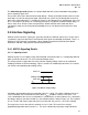
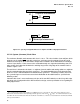
4. Parameter refers to the Space-to-Height ratio of spacing between signal traces
and the height above the associated ground plane. Definitions for microstrip
and stripline traces are described in section 3.5.3.1 .
5. Sum of all interconnect skew contributors, including crosstalk, interconnect
mismatch, etc., across the entire channel (including package and connector).