
Accelerated Graphics Port Interface Specification

AGP3.0 Interface Specification
Rev. 1.0
71
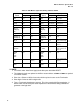
6. Propagation delay must account for all contributors up to the connector pins.
7. Effective impedance incorporates all coupling effects including crosstalk as it is
explained in section 3.5.3.1.
8. This represents the contribution to skew on the motherboard and includes all
causes, not just interconnect.
9. Package information is added here for simple reference. Flip-chip packaging is
highly recommended. For further details, consult section 3.7 on package types
in this chapter.
10. This is the fan-in and fan-out length that does not follow the normal trace
separation requirements in the connector area on the motherboard and the
edge fingers of the graphics card.
11. Characteristic impedance is defined by trace/stackup geometry, electrical
characteristic of PCB materials and their tolerances.
12. Pin-to-trace breakout length should be as short as possible to minimize
negative effects of reduced trace separation.
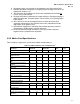
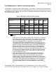
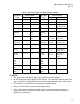
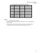
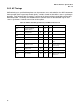
3.5.5 Add-in Card Specifications
Table 34 outlines requirements specific to the add-in card interconnect.
Table 34: Add-in Card Interconnect Requirements
1
Parameter AGP3.0-DT AGP3.0-WS Units Notes
Min Max Min Max
Source Synchronous Signals
Interconnect Length -
Stripline/Microstrip
1.0 1.5 1.0 1.5 inches 1, 2, 3,11
Interconnect Mismatch – strobe-to-
strobe
5 5 mils 4
Interconnect Mismatch – strobe-to-
data
25 25 mils 4
Trace Characteristic Impedance
(Stripline)
50 62 50 62 Ω 10
Trace Characteristic Impedance
(Microstrip)
54 66 54 66 Ω 10
Trace Effective Impedance 48 70 48 70 Ω 7
Data-to-Data Spacing 4/1 4/1 S/H 5
Strobe-to-Strobe Spacing 5/1 4/1 S/H 5
Strobe-to-Data Spacing 5/1 4/1 S/H 5
Pin-to-Trace Breakout 300 300 mils 11
Common Clock Signals
Signal Propagation Delay 0.7 0.7 ns 6
Common Clock Skew 100 100 ps 8
Package Types
Package Types FCBGA, OLGA or BGA FCBGA or OLGA 9
Package Trace Characteristic
Impedance
48 64 48 64 Ω