
Accelerated Graphics Port Interface Specification

AGP3.0 Interface Specification
Rev. 1.0
75
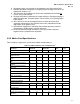
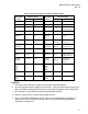
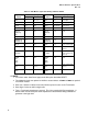
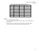
Table 36: AGP Target Signal State During and After RESET
Signal Name AGP3.0 Signaling
Signal Name AGP 2.0 Signaling
AGP3.0 During Reset After Reset
1
AGP2.0 During Reset
After Reset
1
REQ PD or Term Term REQ# Pull-up Pull-up
GNT PD or Term Drive Low GNT# Pull-up Drive High
ST[2:0] PD or Term Drive Low ST[2:0] Pull-up Drive to
determinate state
DEVSEL PD or Term Term DEVSEL# Pull-up Pull-up
AD[31:0]
C#/BE[3:0]
PAR
PD or Term Drive Low or
Term
AD[31:0]
C/BE[3:0]#
PAR
Pull-up Driven (as parked
master)
DBI_LO PD or Term Drive Low or
Term
(Not used) Pull-up
(not used)
Pull-up
(not used)
ADSTBF[1:0]
ADSTBS[1:0]
PD or Term Term ADSTB[1:0]
ADSTB[1:0]#
Pull-up
Pull-down
Float or Driven (as
parked master)
DBI_HI PD or Term Drive Low or
Term
PIPE# Pull-up Pull-up
SBA[7:0] PD or Term Term SBA[7:0]# Pull-up Pull-up or input
disable (Note 2)
SB_STBF
SB_STBS
PD or Term Term SB_STB
SB_STB#
Pull-up
Pull-down
Pull-up idle or
input disable
(Note 2)
FRAME
IRDY
TRDY
STOP
PD or Term Term FRAME#
IRDY#
TRDY#
STOP#
Pull-up Pull-up
RBF
WBF
PD or Term Term RBF#
WBF#
Pull-up Pull-up
PERR
SERR
PD or Term Term PERR#
SERR#
Pull-up Pull-up
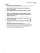
/ NOTES
1 The values under “After Reset” apply to the idle cycles that follow RESET.
2 An AGP2.0 graphics device might not use these pins. They should be pulled up by the core
logic, or the inputs should be disabled until it is known that the graphics chip is driving them.
3 PD, Pull-down = normal AGP2.0 sustainer pull-down (8KΩ nominal)
4 Pull-up = normal AGP2.0 sustainer pull-up (8KΩ nominal)
5 Term = Termination impedance to ground. This is the standard AGP3.0 termination. A
default value must be used prior to the impedance of the terminator being calibrated to
guarantee a low logic level.