
Accelerated Graphics Port Interface Specification

AGP3.0 Interface Specification
Rev. 1.0
78
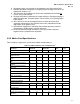
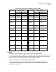
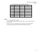
specified nominal value across the entire range between Vss and V
OH
(Refer to Table 45 for
complete details).
5. The driver pull-up impedance must be adjusted to obtain an output swing within the V
OH
specification. More information on driver characteristics can be found in section 3.6.6.1.
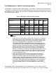
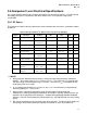
3.6.2 AC Measurement and Test Conditions
Because of the high-speed nature of the AGP3.0 interface, test measurements must be performed on a
tester with highly accurate edge placements (±100ps or better is recommended). Unless otherwise
specified, the reference point for all AC input timing measurements is V
REF
and for all AC output timing
measurements is 0.5V
OH
into a standard test load. The model for the test structure is shown in Figure
3-14. Buffer slew rates can be measured using the same setup used for buffer delay determination.
Buffer
under
test
V
OUT
R
TT
= 50
Ω
Figure 3-14: AGP3.0 Standard Buffer Test Load
R
TT
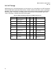
is set equal to the target buffer impedance (50 Ω as shown in the previous diagram).
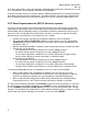
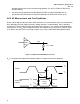
inputs
valid
T
h
T
su
V
clk
V
test
Strobe
Data/Input
Strobe
V
test
V
th
V
tl
V
tl
V
th
Figure 3-15: . Input Timing Measurement