
Accelerated Graphics Port Interface Specification

AGP3.0 Interface Specification
Rev. 1.0
79
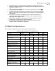
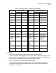
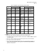
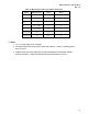
Table 39: Measurement and Test Condition Parameters
Symbol Measure Point Units Notes
V
clk
V
REF
V 1
V
testi
V
REF
V Test level for inputs
V
testo
0.5V
OH
V Test level for outputs
V
th
V
REF
+ 0.200 V 2
V
tl
V
REF
- 0.200 V 2
slew rate max
3.5 V/ns 3
slew rate min 2.0 V/ns 3
/ NOTE
1. V
clk
is a strobe signal in this example.
2. The input timing measurement test is done with at least 0.1 Volts of overdrive greater
than V
il
and V
ih
.
3. Outputs will be measured at the die pad and characterized and simulated with the
loads shown above. Signal slew rate will be measured between V
tl
and V
th
.