
Accelerated Graphics Port Interface Specification

AGP3.0 Interface Specification
Rev. 1.0
84
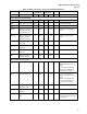
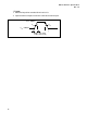
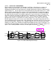
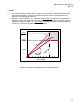
Figure 3-17: Signal Integrity Requirements
V
REF
T
DRIVE
Keep Out
Region
V
RB
V
RB
V
OH
(steady)
V
OL
(steady)
V
IH
(min)
V
IL
(max)
3.6.4.2.1 SPECIAL STROBE SI REQUIREMENTS
As soon as a strobe transition crosses the DC V
IL
or V
IH
limits, the transition must continue
monotonically through the VREF switch point to V
RB
overdrive beyond VREF, outside the shaded keep-out
region of Figure 3-17. The strobe must remain outside the keep-out region for time T
DRIVE
. At this point,
the signal is allowed more noise as long as it does not violate the DC V
IL
and V
IH
limits until the next
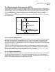
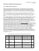
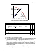
transition. Figure 3-18 shows an example of an allowed signal shelf that exceeds the V
RB
overdrive
requirement. Note that the signal drops below V
RB
a bit later, but well after T
DRIVE
, which is allowed. The
strobe signal settles close to the nominal V
OH
before the next transition. Figure 3-18b shows an
example of noise that exceeds the V
RB
limit, but is allowed since it is beyond the T
DRIVE
requirement.
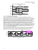
Figure 3-18c and d show cases that are not allowed. In Figure 3-18c, the strobe drops below V
RB
before
T
DRIVE
has elapsed. In Figure 3-18d, the strobe glitches above V
IL
(max), even though the strobe signal
is low for T
DRIVE
. Glitches on Strobe signals are never allowed to violate DC V
IL
or V
IH
, unless the
strobe is fully switching between logic levels.
If the signal in Figure 3-18d had not violated V
IL
(max), it would have been okay, even though the time
from the glitch to the next transition is small. The strobe signal would have met the T
DRIVE
timing
requirements after the last transition and the glitch would not be a voltage or timing violation.
V
RB
V
IH
(min)
T
DRIVE
V
IL
(max)
V
REF
V
REF
T
DRIVE
V
RB
Violations
B
A
C
D
Figure 3-18: Strobe Ringback Examples