
Accelerated Graphics Port Interface Specification

AGP3.0 Interface Specification
Rev. 1.0
95
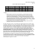
Table 47: Add-in Card Power Supply Limits
Symbol Parameter Condition Min Max Units Notes
Vddq1.5 I/O Supply Voltage I
MAX
= 2.0 A 1.425 1.575 V 1, 2
VCC3.3 3.3 V Power Supply I
MAX
= 6.0 A 3.15 3.45 V
3.3VAUX 3.3 V Auxiliary Supply I
MAX
= 0.375 A 3.15 3.45 V
VCC5 5 V Power Supply I
MAX
= 2.0 A 4.75 5.25 V
VCC12 12 V Power Supply I
MAX
= 1.0 A 11.4 12.6 V
/ NOTE
1. AGP3.0 requires no more than 1.0 amp average V
DDQ
current through the connector.
Sufficient bulk capacitance should be provided on the add-in card to provide for higher
instantaneous current requirements. This allows each add-in card vendor the ability to
determine the correct bulk capacitance. The add-in card should consume no more than 2
amps at any time (from the motherboard). In addition, it is good design practice to limit the
AC current through the AGP connector to improve signal integrity. It is necessary to provide
additional bulk capacitance on the motherboard near the AGP connector. The V
DDQ
delivery
recommendations can be found in the AGP3.0 Design Guide.
2. A universal add-in card may need Vddq3.3 for AGP1.0 signaling. Refer to the AGP2.0
Specification, Revision 2.0 for this case and ECR #54.
The add-in card cannot cause the 3.3V rail voltage on the motherboard to not meet the Vcc3.3 supply
specifications. Minimally, this can be met by ensuring the add-in card draws no more than a maximum
current change of 2.5 amps in any 500 us window of time (exclusive of initial power-up) on the 3.3V rail.
The add-in card could increase the absolute magnitude of its current step by over 2.5A if the short term
average is 2.5 amperes or less, or if it does it in stages that are at least 500us apart, giving the
motherboard/power supply time to respond. Add-in card vendors who exceed these limits must
ensure that the add-in card does not cause the voltage on the motherboard to not meet
regulation specifications. The slew rate at any pin of the connector must be less than 25 A/us. Slew
rates faster than this must be handled by add-in card decoupling. Current pulses lasting less than a
microsecond cannot be resolved by the motherboard, and consequently, the add-in card vendor must
identify if specific cases will be a problem for their design and deal with them accordingly.
The motherboard must respond to any 2.5 amp current step as described above and stay inside the
specified supply tolerance when measured at the AGP connector pins on the motherboard (averaged at
connector pins A9, A16 and A28). The add-in card could increase the absolute magnitude of its current
step by over 2.5 amps if it does so in stages that are at least 500 µs apart, giving the
motherboard/power supply time to respond.