
Alert Standard Format (ASF) Specification


Alert Standard Format (ASF) Specification v2.0 DMTF Document DSP0136
DSP0136 23 April 2003 Page 80 of 94
connection by the device. For example, ASF (bit 5) and IPMI.
Subsystem
Vendor ID
This field may hold a value derived from any of several sources:
• The device manufacturer’s ID as assigned by the SBS
Implementers’ Forum or the PCI SIG.
• The device OEM’s ID as assigned by the SBS Implementers’
Forum or the PCI SIG.
• A value that, in combination with the Subsystem Device ID, can
be used to identify an organization or industry group that has
defined a particular common device interface specification.
Subsystem
Device ID
The subsystem ID identifies a specific interface, implementation, or
device. The party identified by the Subsystem Vendor ID field
defines the Subsystem ID.
Vendor-specific
ID
A unique number per device.
6.2.2 Event Generation and Clearing
Events reported by an ASF sensor must be level events from the alert-sending device
perspective. This behavior allows the Alert Sending Device to detect the state transitions and
send assertion and de-assertion alerts, and allows a managed client to include multiple alert-
sending devices.
An implementer may choose to design a “sticky” event that requires a mechanism to be cleared.
In these cases, the clear mechanism is outside the scope of the ASF specification. An example
of a desired “sticky” event is a “chassis intrusion” detection circuit.
Note: Events monitored under the ASF context are intended to be low frequency and generally
stable and monotonic. This is a general requirement due to the uncertain speed of the SMBus.
This specification does not limit the event transition frequency of a sensor’s event. Instead,
implementers are recommended to implement “sticky” events where critical events may have a
transition frequency that may allow the event to go undetected.
6.2.3 Alert Status
ASF-sensor devices will implement event generation and clearing with the following behavior:
• Sensor must contain an active-high, level-sensitive status register bit for each event; the
sensor may also optionally implement an edge-triggered status bit for host system notification
and event processing.
• The alert-sending device (e.g. NIC) is responsible for edge-detection of an event (i.e. the
alert-sending device must recognize when the alert event is first generated).
• “Sticky” event status bits are cleared by the mechanisms unique to the managed client
system (e.g. BIOS, DMI, CIM). The alert-sending device is not required to clear sticky event
status.
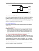
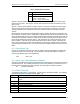
Illustrated below is a conceptual example of an alert event logic structure with the optional edge-
triggered bit for the host. For one event there are two register bits within the sensor device. The
bit in the Poll Alert Register is simply the level-sensitive event. The bit in the Host Alert Register is
implemented as a “sticky” bit; this bit is set when the event transitions from inactive to active and
can only be cleared by some action taken by the host. This bit could also feed additional logic to
generate a host system interrupt.