
Alert Standard Format (ASF) Specification

Alert Standard Format (ASF) Specification v2.0 DMTF Document DSP0136
DSP0136 23 April 2003 Page 91 of 94
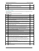
#### Description
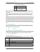
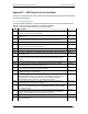
AS20
The device responds to the SMBus Set System State message (see 5.3.2) and
returns the last value written in response to an RMCP System State Request (see
3.2.4.10). If no value is written by the system firmware, the device responds with
a System State value of “Unknown”.
Required
AS21
The device responds to the SMBus Start Watchdog Timer and Stop Watchdog
Timer messages, issuing the associated ASF alert if the timer is not reset within
the required amount of time.
Required
AS22 The device responds to the SMBus Boot Options messages (see 5.2). Required
AS23
The device responds to the SMBus Push messages (with and without
retransmission) and transmits the requested ASF alerts.
Required
AS24
A system board-set device (e.g. soldered onto the motherboard) has an
assignable SMBus device address.
Optional
AS25
A device on a card that plugs into an expansion bus has an assignable SMBus
device address.
Required
AS26
The device supports AS12, AS15, and AS18 features for all system states from
which the device is configurable to accept packets to wake the system.
Required
C.2 Local Alert-Sending Device Configuration Software
The following table identifies the required and optional features for the OS-present configuration
software provided with an alert-sending device:
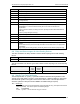
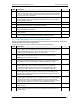
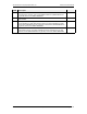
Table D-2 Local Alert Configuration Software Checklist for ASF Implementations
#### Description
CS1
The configuration software programs non-volatile memory for the alert-sending
device with the Minimum Watchdog Reset Value, Minimum ASF Sensor Inter-poll
Wait Time, Manufacturer ID, and System ID values present in the system
firmware’s ACPI implementation (see 4.1.2.1 ASF_INFO).
Required
CS2
The configuration software programs non-volatile memory for the alert-sending
device with the managed client’s UUID, as found in the system firmware’s
SMBIOS System Information structure.
Required
CS3
If the alert-sending device supports system heartbeat messages, the device’s
configuration software provides a user-settable rate at which the messages are
transmitted and a method through which to disable the messages entirely.
Required
CS4
If the managed client supports legacy-device alerts (as described in the system’s
ACPI implementation, see 4.1.2.2 ASF_ALRT) the alert-sending device’s
configuration software enables the device to send PET alerts based on the
legacy-device status. Refer to 4.1.2.2 and 6.1.2 for additional information.
Required
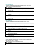
CS5
The configuration software, when running on an ACPI-aware operating system,
sets its alert-sending device’s power-on wait time (via the ACPI SPWT control
method) to the maximum of the device’s fixed time and the value returned by the
GPWT ACPI control method.
Required
CS6
If the managed client supports RMCP control messages (as described in the
system’s ACPI implementation, see 4.1.2.4 ASF_RCTL and 4.1.2.6 ASF_RMCP)
the alert-sending device’s configuration software records the system-specific
information into the device’s non-volatile memory to enable the device to respond
to the messages. Refer to 3.2.4.1 and 3.2.4.2 for additional information.
Required
CS7
The configuration software records the device’s TCP/IP address into its non-
volatile memory.
Required
CS8
The configuration software gathers the TCP/IP address of the management
console to which alerts are sent, and records this address into the device’s non-
volatile memory.
Required