
Alert Standard Format (ASF) Specification

Alert Standard Format (ASF) Specification v2.0 DMTF Document DSP0136
DSP0136 23 April 2003 Page 92 of 94
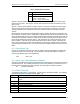
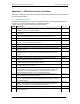
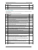
C.3 Legacy Sensor
The following table identifies the required and optional features for an ASF legacy sensor.
Table D-3 Legacy Sensor Checklist for ASF Implementations
#### Description
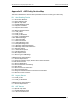
LS1
The alert associated with each sensor contained in the device must be pollable
via an SMBus Byte Read command. Any sensor that reports a value, such as a
voltage sensor, without an associated threshold and alert is not supported as an
ASF legacy sensor.
Required
LS2
Individual status bits in the Read Result value returned by an SMBus Byte Read
identify the device’s alerts.
Required
LS3
All status bits returned by the device that are set to 1b within the Alert Data Mask
published by the system firmware must always be valid. See 6.1.1 for more
information.
Required
LS4
The alert status bits must be either level or automatically cleared after an SMBus
Byte Read, but set again before the next Byte Read if the event is still active. See
6.1.1 for more information.
Required
LS5
The device responds to its address within 4 seconds (the Minimum Legacy
Sensor Poll Time).
Required
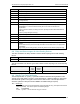
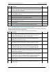
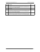
C.4 ASF Sensor
The following table identifies the required and optional features for an ASF sensor.
Table D-4 ASF Sensor Checklist for ASF Implementations
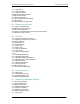
#### Description
SD1 The device is compliant with [SMBUS_2.0]. Required
SD2
The device, present on an expansion-bus card, supports an assignable SMBus
address.
Required
SD2
The device, present on the system board-set (e.g. soldered onto the motherboard),
supports an assignable SMBus address.
Optional
SD3
The device supports the SMBus Device Type Poll message (see 5.3.1), responding
with ASF Function Bits set to 02h to indicate that it is an ASF sensor device.
Required
SD4
The device supports the SMBus Get Event Data and Get Event Status messages
(see 5.1.1).
Required
SD5
The device’s SMBus 2.0 UDID identifies the device as supporting ASF methods by
setting bit 5 of the UDID Interface field to a 1.
Required
SD6
The sensor contains an active-high (logic level 1), level-sensitive status register for
each event reported by the sensor.
Required
SD7
The sensor completes its power-on reset (POR) in 500 milliseconds from detection
of stable supply power.
Required
SD8 The device supports SMBus PEC protocols for ASF-defined messages. Required
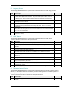
C.5 Remote Control Device
The following table identifies the required and optional features for a system’s remote-control
devices, i.e. the SMBus devices accessed by the alert-sending device to cause the system to
power cycle, reboot, power on, or power off.
Table D-5 Remote Control Device Checklist for ASF Implementations
#### Description
RD1
The device supports the SMBus Byte Write transaction to set the remote-control
action.
Required