
BIOS Settings Glossary version 19
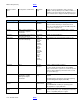
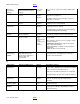
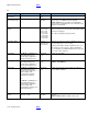
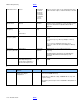
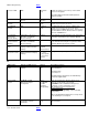
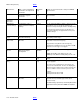
Table Of Contents

BIOS Settings Glossary BACK
V19 – November 2012 BACK
Manufacturer
Main > System Identification
Information > Desktop Board
Information
Information
only
Displays the board manufacturer string from SMBIOS
Type 2 structure.
Manufacturer
Main > System Identification
Information > System
Information
Information
only
Displays the system manufacturer string from SMBIOS
Type 1 structure.
Master Key Hard
Disk Drive
Password
Security
Information
only
Reports if there is a master key hard disk drive password
set.
Max Inverter
Current Limit (%)
Configuration > Video >
Advanced Flat Panel Display
Settings
Numeric
Sets the maximum PWM acceptable to drive the inverter
board, which serves as an upper boundary for the
amount of current powering the monitor’s backlight lamp.
Consult inverter board and monitor specifications for
proper value. Warning: Unsupported values may cause
hardware damage.
Maximum Duty
Cycle
Configuration > Fan Control &
Real-Time Monitoring
Numeric
Selects the maximum duty cycle that the fan will never go
above during normal usage.
Maximum Non-
Turbo Ratio
Performance > Processor
Overrides
Numeric
Maximum Non-Turbo Processor Speed = Maximum Non-
Turbo Ratio x Host Clock Frequency
This parameter along with Host Clock Frequency
determines the maximum processor speed when Intel®
Turbo Boost Technology is not engaged.
ME Wake from S3,
S4, S5
Intel® ME > Intel®
Management Engine
Configuration
• Enable
• Disable
Determines the state of Intel® ME during system sleep
states.
Enable: allows ME to wake during S3, S4 or S5.
Disable: prevents ME from waking during S3, S4 or S5.
Memory
Performance
Information
only
Displays the default, proposed and active memory
voltage.
Memory Channel x
Slot y
Main
Information
only
Displays the installed system memory size in Channel x
Slot y in gigabytes.
One of these lines is displayed for each memory slot
present on the motherboard. The lines are displayed in
order based on the distance of the memory slot from the
processor, with the slots closest to the processor first.
Example:
Memory Channel A Slot 0 2 GB
Memory Channel B Slot 0 1 GB
Memory Correction
Performance > Memory
Overrides
• Non-ECC
• ECC
Allows you to turn error reporting on or off if the system
and all the memory installed supports ECC (Error
Correction Code).
This BIOS setting is present only on Desktop Boards that
support ECC memory when ECC DIMMs are installed.