
Bootable CD-ROM Format Specification

Version 1.0 Copyright 1994 Phoenix Technologies and IBM All Rights Reserved. Page 10
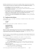
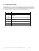
Offset Type Description
0 Byte Boot Indicator. 88 = Bootable, 00 = Not Bootable
1 Byte Boot media type. This specifies what media the boot image is intended to
emulate in bits 0-3 as follows, bits 4-7 are reserved and must be 0.
Bits 0-3 count as follows:
0 No Emulation
1 1.2 meg diskette
2 1.44 meg diskette
3 2.88 meg diskette
4 Hard Disk (drive 80)
5-F Reserved, invalid at this time
2-3 Word Load Segment. This is the load segment for the initial boot image. If this
value is 0 the system will use the traditional segment of 7C0. If this value
is non-zero the system will use the specified segment. This applies to x86
architectures only. For “flat” model architectures (such as Motorola) this
is the address divided by 10.
4 Byte System Type. This must be a copy of byte 5 (System Type) from the
Partition Table found in the boot image.
5 Byte Unused, must be 0
6-7 Word Sector Count. This is the number of virtual/emulated sectors the system
will store at Load Segment during the initial boot procedure.
8-0B D Word Load RBA. This is the start address of the virtual disk. CD’s use
Relative/Logical block addressing.
0C-1F Byte Unused, must be 0.
Figure 3 - Initial/Default Entry
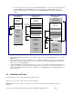
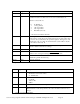
Offset Type Description
0 Byte Header Indicator as follows:
90 -Header, more headers follow
91 - Final Header
1 Byte Platform ID:
0 = 80x86
1=Power PC
2=Mac
2-3 Word Number of section entries following this header
4-1F Character ID string. This identifies a section. This string will be checked by BIOS and
BOOT software. If the string matches, the section should be scanned for boot
images.
Figure 4 - Section Header Entry