
Bootable CD-ROM Format Specification


Version 1.0 Copyright 1994 Phoenix Technologies and IBM All Rights Reserved. Page 11
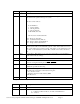
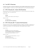
Offset Type Description
0 Byte Boot Indicator. 88 = Bootable, 00 = Not Bootable
1 Byte Boot media type. This specifies what media the boot image emulates in bits 0-32.
Bits 6 and 7 are specific to the type of system.
Bits 0-3 count as follows
0 No Emulation
1 1.2 meg diskette
2 1.44 meg diskette
3 2.88 meg diskette
4 Hard Disk (drive 80)
5-F Reserved, invalid at this time
bit 4 - Reserved, must be 0
bit 5 - Continuation Entry Follows
bit 6 - Image contains an ATAPI driver
bit 7 - Image contains SCSI drivers
2-3 Word Load Segment. This is the load segment for the initial boot image. If this value
is 0 the system will use the traditional segment of 7C0. If this value is non-zero
the system will use the specified segment. This applies to x86 architectures only.
For “flat” model architectures (such as Motorola) this is the address divided by
10.
4 Byte System Type. This must be a copy of byte 5 (System Type) from the Partition
Table found in the boot image.
5 Byte Unused, must be 0
6-7 Word Sector Count. This is the number of virtual/emulated sectors the system will
store at Load Segment during the initial boot procedure.
8-0B D Word Load RBA. This is the start address of the virtual disk. CD’s use
Relative/Logical block addressing.
0C Byte Selection criteria type. This defines a vendor unique format for bytes 0D-1F.
The following formats have currently been assigned:
0 - No selection criteria
1- Language and Version Information (IBM)
2-FF - Reserved
0D-1F Byte Vendor unique selection criteria.
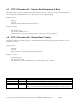
Figure 5 - Section Entry
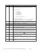
Offset Type Description
0 Byte Extension Indicator. Must be 44
1 Byte Bits 1-4 - Unused
5 - 1 = Extension Record follows, 0 = This is final Extension
6-7 - Unused