
Bootable CD-ROM Format Specification


Version 1.0 Copyright 1994 Phoenix Technologies and IBM All Rights Reserved. Page 19
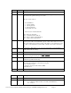
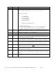
Offset Type Description
0 Byte Packet Size, currently 13
1 Byte Boot media type. This specifies what media the boot image is intended to
emulate in bits 0-3. Bits 6 and 7 are specific to the type of system.
Bits 0-3 count as follows:
0 - No Emulation
1 - 1.2 meg diskette
2 -1.44 meg diskette
3 -2.88 meg diskette
4 -Hard Disk (drive C)
5-F-Reserved, invalid at this time
bits 4-5 - Reserved, must be 0
bit 6 - Image contains an ATAPI driver, bytes 8 & 9 refer to IDE interface
bit 7 - Image contains SCSI drivers, bytes 8 & 9 refer to SCSI interface
2 Byte Drive Number. This is the drive number on which emulation is being initiated or
terminated. This must be 0 for a floppy image, 80 for a bootable hard disk, and
81-FF for a “non-bootable” or “no emulation” drive.
3 Byte Controller Index. This specifies the controller number of the specified CD drive.
4-7 Dword Logical Block Address for the disk image to be emulated.
8-9 Word Device Specification. For SCSI controllers byte 8 is the LUN and PUN of the CD
Drive, byte 9 is the Bus number. For IDE controllers the low order bit of byte 8
specifies master/slave device, 0 = master.
A-B Word User Buffer Segment. If this field is non-zero it specifies the segment of a user
supplied 3k buffer for caching CD reads. This buffer will begin at Segment:0.
C-D Word Load Segment. This is the load address for the initial boot image. If this value is
0 the system will use the traditional segment of 7C0. If this value is non-zero the
system will use the specified address. This field is only valid for function 4C
E-F Word Sector Count. This is the number of virtual sectors the system will store at Load
Segment during the initial boot procedure. This field is only valid for function 4C
10 Byte Bits 0-7 of the cylinder count. This should match the value returned in CH when
INT 13 function 08 is invoked.
11 Byte This is the value returned in the CL register when INT 13 function 08 is invoked.
Bits 0-5 are the sector count. Bits 6 and 7 are the high order 2 bits of the cylinder
count.
12 Byte This is the head count, it should match the value in DH when INT 13 Function 08
is invoked.
Figure 9. - Specification Packet