
Front Panel I/O Connectivity Design Guide


Front Panel I/O Connectivity Design Guide
32
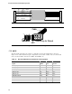
3.3.3 1394 Header Design
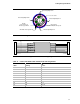
The 1394 header consists of a keyed shrouded (blue for 1394A, red for 1394B) 2x10 stake pin
header (100-mil pitch) with key locations on pin 9. Note that pin 1 location relative to shroud key
is opposite that of the USB header shown in Figure 7 and is intended to prevent 1394 cables from
attaching to USB headers and visa versa.
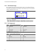
Figure 9. Front Panel IEEE-1394A/B Connector (Top View)
Manufacturer's Part Numbers:
1394A: (Blue Color) Wieson Technologies 2120C888-045G (or equivalent) (lead-free)
1394B: (Red Color) Wieson Technologies 2120C888-047G (or equivalent) (lead-free)
3.3.4 Pin Assignments
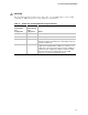
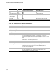
Table 10. Front Panel IEEE-1394A Connector
Pin Signal Name Pin Signal Name
1 TPA+ 2 TPA-
3 Ground 4 Ground
5 TPB+ 6 TPB-
7 +12V (Fused) 8 +12V (Fused)
9 Key (no pin) 10 Ground
Note: IEEE-1394 ports may be assigned as needed.
Table 11. Front Panel IEEE-1394B Connector
Pin Signal Name Pin Signal Name
1 TPA+ 2 TPA-
3 TPA_REF 4 TPB_REF
5 TPB+ 6 TPB-
7 +12V (Fused) 8 +12V (Fused)
9 Key (no pin) 10 Ground
Note: IEEE-1394 ports may be assigned as needed.