
Front Panel I/O Connectivity Design Guide


35
4 Cabling Design Guidelines
What This Chapter Contains
4.1 Introduction .................................................................................................................. 35
4.2 Switch/LED Cable ........................................................................................................ 35
4.3 Front Panel Audio Cable .............................................................................................. 36
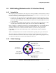
4.4 USB Cabling (Motherboard to I/O Interface Board) .....................................................39
4.1 Introduction
This chapter contains reference cable designs for the switch/LED and audio cable that are
compatible with the connector pinouts described in Chapters 2 and 3.
NOTE
To prevent cable unseating, cables should be secured within the system. Tie wraps and/or sheet
metal features could be used to implement this. Cables that are permanently attached to the front
panel interface board could also be implemented, however the interface to the motherboard should
remain as specified.
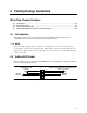
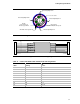
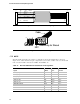
4.2 Switch/LED Cable
Figure 10 shows the proper use of the switch/LED header. Great flexibility in cabling is permitted
as long as this diagram is followed.
P1
21
3 4
65
87
9
(YELLOW)
HARD DRIVE LED
(GREEN) / (YELLOW)
POWER/SLEEP/MESSAGE WAITING LED
POWER
SWITCH
RESET
SWITCH
KEY
Figure 10. Switch/LED Cable